17
(V – VEE - V )
Rg ≥ ––C–C–––––––––O––L–
IOLPEAK
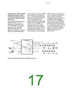
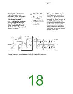
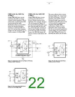
Selecting the Gate Resistor
(Rg) to Minimize IGBT
Switching Losses. (Discussion
applies to HCPL-3120, HCPL-
J312 and HCNW3120)
Step 1: Calculate Rg Minimum
from the IOL Peak Specifica-
tion. The IGBT and Rg in Figure
26 can be analyzed as a simple
RC circuit with a voltage supplied
by the HCPL-3120.
The VOL value of 2 V in the pre-
vious equation is a conservative
value of VOL at the peak current
of 2.5A (see Figure 6). At lower
Rg values the voltage supplied by
the HCPL-3120 is not an ideal
voltage step. This results in lower
peak currents (more margin)
than predicted by this analysis.
When negative gate drive is not
used VEE in the previous equation
is equal to zero volts.
(V – VEE - 2 V)
= ––C–C––––––––––––
IOLPEAK
(15 V + 5 V - 2 V)
= ––––––––––––––––––
2.5 A
= 7.2 Ω 8 Ω
HCPL-3120
+5 V
1
2
3
4
8
V
= 15 V
CC
+ HVDC
270 Ω
0.1 µF
+
–
7
Rg
Q1
= -5 V
3-PHASE
AC
CONTROL
INPUT
6
5
V
EE
–
+
74XXX
OPEN
COLLECTOR
Q2
- HVDC
Figure 26. HCPL-3120 Typical Application Circuit with Negative IGBT Gate Drive.

 ETC [ ETC ]