PIC12F510/16F506
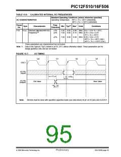
TABLE 13-6: CALIBRATED INTERNAL RC FREQUENCIES
Standard Operating Conditions (unless otherwise specified)
Operating Temperature -40°C ≤ TA ≤ +85°C (industrial),
-40°C ≤ TA ≤ +125°C (extended)
AC CHARACTERISTICS
Param
Freq.
Tolerance
Sym
Characteristic
Min Typ(1) Max* Units
Conditions
No.
F10
FOSC Internal Calibrated INTOSC
Frequency(1)
±1%
±2%
7.92 8.00 8.08 MHz VDD = 3.5V TA = 25°C
7.84 8.00 8.16 MHz 2.5V ≤ VDD ≤ 5.5V
0°C ≤ TA ≤ +85°C
7.60 8.00 8.40 MHz 2.0V ≤ VDD ≤ 5.5V
-40°C ≤ TA ≤ +85°C (Ind.)
±5%
-40°C ≤ TA ≤ +125°C (Ext.)
*
These parameters are characterized but not tested.
Note 1: Data in the Typical (“Typ”) column is at 5V, 25°C unless otherwise stated. These parameters are for
design guidance only and are not tested.
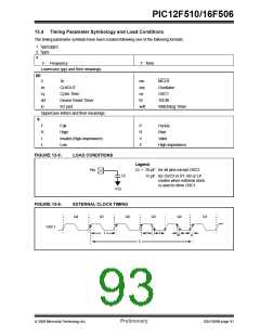
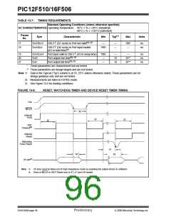
FIGURE 13-7:
I/O TIMING
Q1
Q2
Q3
Q4
OSC1
I/O Pin
(input)
17
18
19
I/O Pin
(output)
New Value
Old Value
20, 21
Note:
All tests must be done with specified capacitive loads (see data sheet) 50 pF on I/O pins and CLKOUT.
© 2006 Microchip Technology Inc.
Preliminary
DS41268B-page 93

 ETC [ ETC ]