Data Sheet
June 2002
TMXF28155 Supermapper
155/51 Mbits/s SONET/SDH x28/x21 DS1/E1
17 TMUX Functional Description (continued)
■ Pointer increments and decrements will be counted and presented to the microprocessor as follows:
— Pointer increments and decrements will be monitored and counted internally.
— The internal and latched counts will be forced to clear (0x00) if TMUX_RLOP[3—1] = 1 (Table 102 on
page 94) or TMUX_RPAIS[3—1] = 1 (Table 102), where [3—1] designates the tributary number.
— Upon the configured performance monitoring interval, raw counts are transferred to holding registers for
pointer increments (TMUX_RPTR_INC[1—3][10:0] (Table 139 on page 123)) and decrements
TMUX_RPTR_DEC[1—3][10:0] (Table 140 on page 123), allowing access by the microprocessor. The raw
counters will reset (to 0x00).
— Depending on the value of SMPR_SAT_ROLLOVER (Table 77 on page 70) in the microprocessor interface
block, the internal running counts saturate at their maximum value or rollover.
— However, increment and decrement event indications should be ignored during LOP station.
■ The current pointer state is read from TMUX_RLOP[3—1] and TMUX_RPAIS[3—1]. Any changes in pointer con-
dition are read from the delta state bits TMUX_RLOPD[3—1] and TMUX_RPAISD[3—1] (Table 93 on page 83).
The associated interrupt mask bits are TMUX_RLOPM[3—1] (Table 97 on page 91) and TMUX_RPAISM[3—1]
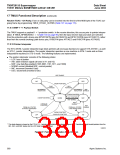
(Table 97 on page 91). When the device is receiving a concatenated signal (STM-1(AU-3)), the receive concate-
nation mode register bit, TMUX_RCONCATMODE (Table 105 on page 97), must be set for the concatenation
state machines (register bits TMUX_CONCAT_STATE[3—2][1:0] (Table 102 on page 94)) on ports 2 and 3 to
contribute to pointer evaluation. This state machine implements the pointer interpretation algorithm described in
ETS 300 417-1-1: January 1996 - Annex B.
17.5.16 Path Monitoring Functions
The following sections describe the path monitoring functions. For STM-1 signals, the values corresponding to
STS-1 #1 are the relevant signals. For STS-3 input data, there are three versions of each path monitor, one corre-
sponding to each STS-1. The mode bits are applied to the monitors of all three STS-1s.
J1 Monitor. J1 (path trace) monitoring has six different monitoring modes controlled by TMUX_J1MONMODE[2:0]
(Table 105 on page 97). The J1 monitoring mode for all three STS-1s within an STS-3 signal is the same.
■ TMUX_J1MONMODE[2:0] = 000: The TMUX latches the value of the J1 byte every frame for a total of 64 bytes
in TMUX_J1DMON[1—3][1—64][7:0] (Table 147 on page 124, Table 148, and Table 149). The TMUX compares
the incoming J1 byte with the next expected value (the expected value is obtained by cycling through the previ-
ously stored 16 received bytes in round-robin fashion). The TMUX will perform a byte-by-byte comparison and, if
different, set the path trace identifier state register bit(s), TMUX_RTIMP[1—3] (Table 102 on page 94). The state
bit is cleared at a single byte match. Any change to the path trace identifier is reported in TMUX_RTIMPD[1—3]
(Table 93 on page 83) with interrupt mask bits, TMUX_RTIMPM[1—3] (Table 97 on page 91).
■ TMUX_J1MONMODE[2:0] = 001: This is the SONET framing mode. The hardware looks for the 0x0A character
to indicate that the next byte is the first byte of the path trace message. The J1 byte message is continuously
written into registers, TMUX_J1DMON[1—3][1—64][7:0], with the first byte residing at the first address. If any
received byte does not match the previously received byte for its location, then the state bit(s),
TMUX_RTIMP[1—3], is set. Any change to the path trace identifier is reported in TMUX_RTIMPD[1—3], with
interrupt masks bits, TMUX_RTIMPM[1—3].
■ TMUX_J1MONMODE[2:0] = 010: This is the SDH framing mode. The hardware looks for the byte with the MSB
set to one, which indicates that the next byte is the second byte of the message. The rest of operation is the
same as in SONET framing mode, except that there are 16 bytes instead of 64.
■ TMUX_J1MONMODE[2:0] = 011: A new J1 byte (TMUX_J1DMON[1][7:0]) will be detected after a number of
consecutive consistent occurrences of a new pattern (determined by the value in TMUX_CNTDJ1[3:0]
(Table 109 on page 101)) in the J1 overhead byte. Any changes to this byte must be reported in
TMUX_RTIMPD[1—3] with the interrupt mask bits, TMUX_RTIMPM[1—3]. The delta bit(s) in this mode indicate
a change in state for the TMUX_J1DMON[1][7:0] byte and the state bits, TMUX_RTIMP[1—3], are not used.
Agere Systems Inc.
383

 ETC [ ETC ]