TMXF28155 Supermapper
155/51 Mbits/s SONET/SDH x28/x21 DS1/E1
Data Sheet
June 2002
17 TMUX Functional Description (continued)
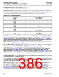
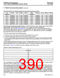
REI-P Detection. Bits [7:4] of the G1 byte are allocated for use as a path remote error indication function (REI-P).
■ For STS-1 and STM-1 signals, bits [7:4] of the G1 byte are allocated for REI-P, which conveys the error count
detected by the PTE (using the path BIP-8 code B3) back to its peer PTE as shown in Table 537.
Table 537. STS-1 P-REI Interpretation
G1[7:4] Code
0000
0001
0010
0011
Code Interpretation
0 (no errors)
1
2
3
0100
0101
0110
4
5
6
0111
7
8
1000
1001
. . .
0 (no errors)
. . .
1111
0 (no errors)
The TMUX allows access to the G1-REI errored bit count for each STS-1/STM-1 in TMUX_G1ECNT[1—3][15:0]
(Table 138 on page 122), which is the accumulated error count from G1[3:0] byte of the STS-1/STM-1 signal. The
counter(s) will count in bit or block mode, depending on the value of TMUX_BITBLKG1 (Table 105 on page 97).
Upon the configured performance monitor (PM) interval, the value of the internal running counter is placed into the
holding registers TMUX_G1ECNT[1—3][15:0] and then cleared. Depending on the value of
SMPR_SAT_ROLLOVER (Table 77 on page 70) in the microprocessor interface block, the internal counter will
either roll over or stay at its maximum value until cleared.
Path User Byte F2 Monitor. The TMUX monitors the path user channel in the F2 byte of each STS-1/STM-1. The
F2 byte(s) will be stored in TMUX_F2MON0[1—3][7:0] (Table 114, starting on page 103). Each register will be
updated after a number of consecutive frames of identical F2[7:0], as determined by the value in
TMUX_CNTDF2[3:0] (Table 109 on page 101). That is, the 8-bit pattern must be identical for the programmed
number of frames prior to updating the F2 register. Any change to F2 monitor registers will be reported in
TMUX_RF2MOND[1—3] (Table 93) with interrupt mask bits, TMUX_RF2MONM[1—3] (Table 97 on page 91). The
TMUX also maintains a history of the previous valid F2 byte in TMUX_F2MON1[1—3][7:0] (Table 114). The contin-
uous N-times detection counter(s) will be reset to 0 upon the transition of the framer into the out of frame state.
H4 Multiframe Indicator. The H4 byte is allocated for use as a mapping specific indicator byte. For VT-structured
SPEs, this byte is used as a multiframe indicator.
The TMUX passes the H4 byte of each STS-1 onto the low-speed telecom bus so that it can be monitored by the
VT mapper block. The TMUX also indicates when the H4 byte(s) has a value of 0x01 by asserting the RLSV1 out-
put pin (pin number W4) on the telecom bus during that frame.
Note: The three H4 bytes of an STS-3 signal can occur at any time with respect to one another within a frame.
Path User Byte F3 Monitor. The TMUX monitors the second path user channel in the F3 byte for each
STS-1/STM-1. The F3 byte(s) for each STS-1/STM-1 is stored in TMUX_F3MON0[1—3][7:0] (Table 114 on
page 103). Each register will be updated after a number determined by the value in TMUX_CNTDF3[3:0]
(Table 109 on page 101) of consecutive frames of identical F3[7:0] monitor bytes on that particular STS-1. That is,
the 8-bit pattern must be identical for the programmed number of frames prior to updating the F3 register.
386
Agere Systems Inc.

 ETC [ ETC ]