TMXF28155 Supermapper
155/51 Mbits/s SONET/SDH x28/x21 DS1/E1
Data Sheet
June 2002
17 TMUX Functional Description (continued)
Receive TOAC—OH Parity. Even or odd parity can be inserted into the first bit of the MSB byte of the TOAC out-
going frame by programming TMUX_RTOAC_OEPINS (Table 127 on page 115).
17.5.14 MSP 1 + 1 Payload Switch
The TMUX supports a payload 1 + 1 protection switch. In the receive direction, this occurs prior to pointer interpre-
tation. If TMUX_RPSMUXSEL1 = 1 (Table 103 on page 96), then the input receive data and clock are selected
from the protection path: device pins RPSD155P/N (pins AD10/AE10) and RPSC155P/N (pins AC10/AD11), rather
than from the normal (working) path device pins, RHSDP/N (pins AF7/AE7) and RHSCP/N (pins AC7/AD8).
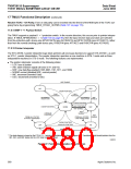
17.5.15 Pointer Interpreter
The STS-3/STM-1 pointer interpreter logic block performs all necessary functions to support STS-3/STM-1, as well
as STS-1, pointer interpretation. The pointer interpreter operates as one machine in STM-1 mode and as three
independent machines in STS-3 mode. The following features are implemented:
■ The pointer interpreter consists of the following states:
— LOP: loss of pointer
— AIS: alarm indiction signal (all ones in H1 and H2)
— NDF: new data flag enabled (1001,0001,1101,1011, and 1000)
— NORM: normal (disabled NDF, normal pointer)
— INC: increment (inverted I bits)
— DEC: decrement (inverted D bits)
NDF ENABLE
INC
DEC
3 NEW POINTERS
3 ANY
POINTERS
3 ANY
POINTERS
INCREMENT
INDICATION
DECREMENT
NDF
INDICATION ENABLE
3 NEW POINTERS
3 ANY POINTERS
NDF ENABLE
3 NEW POINTERS
NORM
NDF
NDF
ENABLE
8 INVALID
POINTERS
NDF
ENABLE
FROM ALL STATES
8 INVALID POINTERS*
FROM ALL STATES
3 AIS INDICATIONS
3 NEW POINTERS
8 INVALID POINTERS
LOP
AIS
8 NDF ENABLE
* This state diagram is based on the ETS-417-1-1 pointer interpretation state diagram (Figure B.1). Transitions of eight invalid pointers from the
INC, DEC, and NDF states into the LOP state have been added.
5-9007(F)
Figure 27. Pointer Interpretation State Diagram
380
Agere Systems Inc.

 ETC [ ETC ]