Data Sheet
June 2002
TMXF28155 Supermapper
155/51 Mbits/s SONET/SDH x28/x21 DS1/E1
17 TMUX Functional Description (continued)
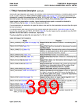
Table 536. STS Signal Label Defect Conditions
Provisioned STS PTE
Functionality, Expected C2
Received Payload Label
(C2 in hex)
Defect
TMUX_FORCEC2DEF = 1
(Table 107 on page 99)
Any Equipped Functionality
Any Equipped Functionality
Equipped—Nonspecific
Unequipped (00)
TMUX_RUNEQP
None
No Change
No Change
No Change
No Change
Equipped—Nonspecific (01)
Any Value (02 to E0, FD to FE)
None
Any Payload Specific Code
The Same Payload Specific
Code (02 to E0, FD to FE)
None
Any Payload Specific Code
A Different Payload Specific
Code (02 to E0, FD to FE)
TMUX_RPLMP
None
No Change
TMUX_RPLMP
No Change
Equipped—Nonspecific (01) or PDI, 1 to 27 VTx Defects
VT-Structured STS-1 (02)
(E1 to FB)
Any Payload Specific Code
Except VT-Structured
STS-1 (02)
PDI, 1 to 27 VTx Defects
(E1 to FB)
TMUX_RPLMP
Any Equipped Functionality
PDI, 28 VT1.5 Defects or 1
Non-VT Payload Defect (FC)
None
None
TMUX_RPLMP
TMUX_RPLMP
Any Equipped Functionality
Reserved (FF)
TMUX_FORCEC2DEF[2:0] will force path payload label mismatch defects on those conditions that are shown in
Table 536.
The continuous N-times detection counter(s) will be reset to 0 upon the transition of the framer into the out of frame
state.
RDI-P Detection. A remote defect indication-path (RDI-P) signal indicates to STS path terminating equipment
(PTE) that its peer STS PTE has detected a defect on the signal that it originated. The TMUX supports a 1-bit
RDI-P code as well as a 3-bit enhanced RDI-P code; the mode is selectable using the TMUX_REPRDI_MODE
(Table 105 on page 97). If TMUX_REPRDI_MODE = 0, then the 1-bit code is supported, and if
TMUX_REPRDI_MODE = 1, then the 3-bit enhanced path RDI code is supported.
The TMUX monitors for a 1-bit RDI-P code in G1[3] or a 3-bit enhanced remote defect indication (RDI-P) condition
in G1[3:1]. The current value of the path RDI state will be detected after a number of consecutive occurrences
determined by the value in TMUX_CNTDRDIP[3:0] (Table 109 on page 101). The current value(s) will be stored in
TMUX_RDIPMON[1—3][2:0]] (Table 114 on page 103), for nonenhanced RDI-P mode, and the current value(s)
will be stored in TMUX_RDIPMON[1—3][2:0], for enhanced RDI-P mode. Any change to
TMUX_RDIPMON[1—3][2:0] will be reported in TMUX_RRDIPD[1—3] with interrupt mask
bits,TMUX_RRDIPM[1—3] (Table 97 on page 91).
The continuous N-times detection counter(s) will be reset to 0 upon the transition of the framer into the out of frame
state.
Agere Systems Inc.
385

 ETC [ ETC ]