Data Sheet
June 2002
TMXF28155 Supermapper
155/51 Mbits/s SONET/SDH x28/x21 DS1/E1
17 TMUX Functional Description (continued)
The transmit TTOAC allows the users to insert the following overhead bytes: E1, F1, D1—D3, D4—D12, S1, and
E2. Even or odd parity is checked over all bytes. Bytes which are not enabled for insertion are set to an all-ones or
all-zeros stuff value.
The data communication channels D1—D3 or D4—D12 may also be received via the TTOAC interface. In this
mode, the TTOAC channel will comprise a serial 192 kbits/s or a 576 kbits/s data stream.
The insertion (overwrite by TOAC) of programmed S1, F1, J0, Z0-2, and Z0-3 bytes can be enabled via registers.
Automatic insertion of M0/M1 may also be inhibited via registers. A protection switch selects the REI-L value for
insertion to be taken from the protection board rather than from the receive side. The entire APS value or K2[2:0]
can be inserted via writable registers. Automatic RDI insertion is supported with individual inhibit for each contribu-
tor. A protection switch selects the RDI-L value for insertion to be taken from the protection board rather than from
the receive side. B1 and B2 BIP-8 values are calculated and inserted. Both values can be optionally inverted.
ttoac clk
ttoac sync
ttoac data
0784(F)
Figure 23. TMUX TTOAC and RTOAC Timing Diagram
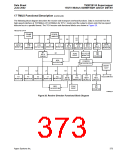
HIGH-SPEED
SONET/SDH INTERFACE
TMUX
TMUX RDI_P, REI_P
TMUX RDI_L, REI_L
STS-3/STM-1
OR STS-1
TELECOM BUS
STS-1/TUG-3
(TIME SLOT #1)
STS-1/TUG-3
(TIME SLOT #2)
STS-1/TUG-3
(TIME SLOT #3)
SPE
MAPPER
DS3
M13
TUG-2
VT/TU
MAPPER
VT MPR RDI_L, REI_L
VT MPR RDI_P, REI_P
DEVICE #1
DEVICE #2
DEVICE #3
5-9004(F)
Figure 24. High-Level TMUX Interconnect
Agere Systems Inc.
371

 ETC [ ETC ]