TMXF28155 Supermapper
155/51 Mbits/s SONET/SDH x28/x21 DS1/E1
Data Sheet
June 2002
17 TMUX Functional Description (continued)
17.4 TMUX Transmit Path Overview
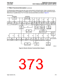
The TMUX transmit path is depicted in the top half of Figure 25 on page 372. The transmit path of the TMUX imple-
ments the inverse function to the receive path. Transmit input traffic at the telecom bus interface from up to three
STS-1/TUG-3 paths is managed via the transmit path bus control circuitry. Transmit traffic, alarms, or unequipped
indication information is inserted as needed depending on the status and provisioning of the device. The 3:1 multi-
plexer provides byte interleave multiplexing of the incoming traffic and insertion of the path overhead bytes. A serial
path provides input for the transmit protection traffic and the framer and serial-to-parallel converter formats this traf-
fic for input to the transmit MSP 1 + 1 payload switch. The selected output from the transmit MSP 1 + 1 switch is
input to the transport overhead insert block and the parallel-to-serial converter sends a serial stream to the device
output. The TMUX transmit path provides path overhead byte insertion and transport overhead byte insertion via
the respective POAC insert and TOAC insert interfaces.
Local clock and frame generation control circuitry is implemented in the TMUX for controlling the STS-1, STS-3,
and STM-1 termination and generation functions. Internal loopbacks in the TMUX provide near-end line loopback
and far-end line loopback capability.
17.4.1 Transmit Telecom Bus
The transmit side of Supermapper drives a clock and three sync signals (SPE, J0J1V1, and V1) onto the telecom
bus. These signals control when the internal SPE mapper or one of the mate devices talks on the data bus.
Because it is on the receive side, the transmit telecom bus operates at 19.44 MHz for STS-3/STM-1 modes and at
6.48 MHz for STS-1 mode. The TMUX communicates with up to three VT/VC mappers, via an 8-bit data word and
an odd/even parity bit from the telecom bus. The data consists of the STS-1/TUG-3 from up to three mappers,
each in its own time slot, or it carries one single STS-1 signal. A 51.84 MHz low-speed clock and sync are also out-
put.
Transmit High-Order Path Overhead Generation and TPOAC Insert. In the transmit direction, J1 path trace
byte insertion, B3 byte calculation and insertion, C2 signal label byte insertion, REI-P and RDI-P insertion; F2 byte
insertion, H4 multiframe byte insertion, F3 path user byte insertion, K3 byte insertion, N1 byte insertion, and AIS-P
insertion via POAC or software control is supported. The transmit TPOAC allows insertion of all overhead bytes
other than the B3 byte, which is automatically calculated. Even or odd parity is checked over all bytes. Bytes which
are not enabled for insertion are set to an all-ones or all-zeros stuff value. Transport path overhead bytes are
added to the payload stream during multiplexing in the byte interleave multiplexer.
Transmit Byte Interleave Multiplexer. In STS-3/STM-1 mode, the transmit byte interleave multiplexer block multi-
plexes up to three STS-1/TUG3 signals to form a SONET/SDH STS-3/STM-1 structured signal. The STS-3/STM-1
multiplexer function processes the input bytes in the order in which they are presented on the transmit telecom bus
and multiplexes these bytes into a single high-speed stream. Grooming of the VTs/VCs is performed in the SPE
mapper of each of the three devices. High-order path overhead bytes are interleaved with the data traffic during the
byte interleave multiplexing.
Transmit Payload Framer and MSP 1 + 1 Payload Switch. In the transmit direction, the MSP 1 + 1 switch func-
tion incorporates dual MSP 1 + 1 payload switch structures. In operation, the traffic from the transmit byte inter-
leave multiplexer is presented to both MSP 1 + 1 payload switches. The output of the signal from the 3:1 multiplex
is broadcast to both switch paths, and the output of the receive payload framers is also input respectively to one of
the two switch paths. For normal operation, one of the two outputs from the two MSP 1 + 1 blocks is selected. The
path from the receive framer to the MSP switch structures provides a means to perform far-end loopback.
Transmit Transport Overhead Generation and TTOAC Insert. The transmit transport overhead generator per-
forms TTOAC byte insertion, sync status byte (S1) insertion, M0/M1—REI-L insertion, K1 and K2 byte insertion,
AIS-L insertion, B2 byte calculation and insertion, F1 byte insertion, B1 byte generation and error insertion, scram-
bling, J0 byte insertion control, and A2 byte error insertion. All insert control functions that are inhibited will option-
ally insert either an all-zeros or an all-ones word.
370
Agere Systems Inc.

 ETC [ ETC ]