a-Si TFT LCD Single Chip Driver
240RGBx320 Resolution and 262K color
ILI9325
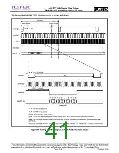
RGB interface mode.
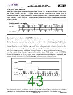
4. In 6-bit RGB interface mode, each of RGB dots is transferred in synchronization with a DOTCLK input. In
other words, it takes 3 DOTCLK inputs to transfer one pixel. Be sure to complete data transfer in units of 3
DOTCLK inputs in 6-bit RGB interface mode.
5. In 6-bit RGB interface mode, data of one pixel, which consists of RGB dots, are transferred in units of
3 DOTCLK. Accordingly, set the cycle of each signal in 6-bit interface mode (VSYNC, HSYNC, ENABLE,
DB[17:0]) to contain DOTCLK inputs of a multiple of 3 to complete data transfer in units of pixels.
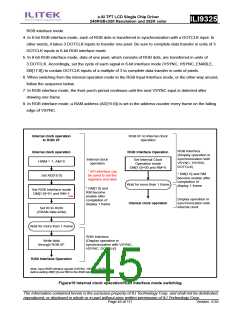
6. When switching from the internal operation mode to the RGB Input Interface mode, or the other way around,
follow the sequence below.
7. In RGB interface mode, the front porch period continues until the next VSYNC input is detected after
drawing one frame.
8. In RGB interface mode, a RAM address (AD[15:0]) is set in the address counter every frame on the falling
edge of VSYNC.
Internal clock operation
to RGB I/F
RGB I/F to Internal clock
operation
RGB Interface
Internal clock operation
HWM = 1, AM=0
RGB Interface Operation
(Display operation in
synchronization with
VSYNC, HSYNC,
DOTCLK)
Internal clock
operation
Set Internal Clock
Operation mode
DM[1:0]=00 and RM=0
* SPI interface can
be used to set the
registers and data
* DM[1:0] and RM
become enable after
completion of
Set AD[15:0]
Wait for more than 1 frame
Internal clock operation
display 1 frame
* DM[1:0] and
RM become
enable after
completion of
display 1 frame
Set RGB Interface mode
DM[1:0]=01 and RM=1
Note
Display operation in
synchronization with
internal clock
Set IR to R22h
(GRAM data write)
Wait for more than 1 frame
RGB Interface
Write data
through RGB I/F
(Display operation in
synchronization with VSYNC,
HSYNC, DOTCLK)
RGB Interface Operation
Note: Input RGB Interface signals (VSYNC, HSYNC, DOTCLK)
before setting DM[1;0] and RM to the RGB interface mode
Figure19 Internal clock operation/RGB interface mode switching
The information contained herein is the exclusive property of ILI Technology Corp. and shall not be distributed,
reproduced, or disclosed in whole or in part without prior written permission of ILI Technology Corp.
Page 45 of 111
Version: 0.35

 ETC [ ETC ]