a-Si TFT LCD Single Chip Driver
240RGBx320 Resolution and 262K color
ILI9325
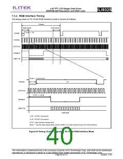
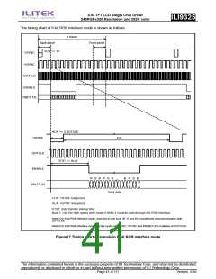
The timing chart of 6-bit RGB interface mode is shown as follows.
1 frame
Back porch
VLW >= 1H
Front porch
VSYNC
HSYNC
DOTCLK
ENABLE
DB[17:12]
HLW >= 3 DOTCLK
//
//
HSYNC
1H
DOTCLK
ENABLE
DB[17:12]
DTST >= HLW
//
R G B R G B
B R G B
//
Valid data
VLW: VSYNC low period
HLW: HSYNC low period
DTST: data transfer startup time
Note 1: Use the high speed write mode (HWM=1) to write data through the RGB interface.
Note 2) In 6-bit RGB interface mode, each dot of one pixel (R, G and B) is transferred in synchronization with
DOTCLKs.
Note 3) In 6-bit RGB interface mode, set the cycles of VSYNC, HSYNC and ENABLE to 3 multiples of DOTCLKs.
Figure17 Timing chart of signals in 6-bit RGB interface mode
The information contained herein is the exclusive property of ILI Technology Corp. and shall not be distributed,
reproduced, or disclosed in whole or in part without prior written permission of ILI Technology Corp.
Page 41 of 111
Version: 0.35

 ETC [ ETC ]