a-Si TFT LCD Single Chip Driver
240RGBx320 Resolution and 262K color
ILI9325
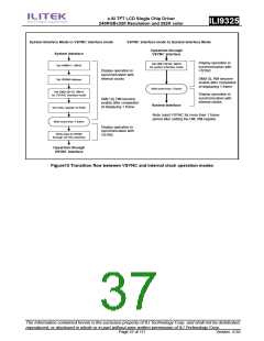
System Interface Mode to VSYNC interface mode
VSYNC interface mode to System Interface Mode
Opeartion through
VSYNC interface
System Interface
Display operation in
synchronization with
VSYNC
Set DM[1:0]=00, RM=0
for system interface mode
Set HWM=1, AM=0
Display operation in
synchronization with
internal clocks
DM[1:0], RM become
enable after completion
of displaying 1 frame
Set GRAM Address
Wait more than 1 frame
Set DM[1:0]=10, RM=0
for VSYNC interface mode
Display operation in
synchronization with
internal clocks
DM[1:0], RM become
enable after completion
of displaying 1 frame
System Interface
Set index register to R22h
Wait more than 1 frame
Note: input VSYNC for more than 1 frame
period after setting the DM, RM register.
Display operation in
synchronization with
VSYNC
Write data to GRAM
through VSYNC interface
Opeartion through
VSYNC interface
Figure13 Transition flow between VSYNC and internal clock operation modes
The information contained herein is the exclusive property of ILI Technology Corp. and shall not be distributed,
reproduced, or disclosed in whole or in part without prior written permission of ILI Technology Corp.
Page 37 of 111
Version: 0.35

 ETC [ ETC ]