a-Si TFT LCD Single Chip Driver
240RGBx320 Resolution and 262K color
ILI9325
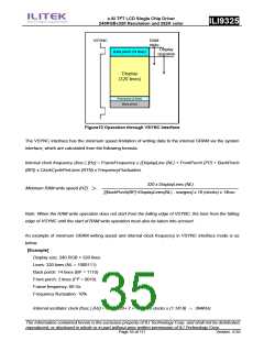
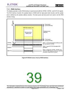
VSYNC
RAM
Write
Display
operation
Back porch (14 lines)
Display
(320 lines)
Front porch (2 lines)
Black period
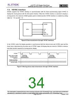
Figure12 Operation through VSYNC Interface
The VSYNC interface has the minimum speed limitation of writing data to the internal GRAM via the system
interface, which are calculated from the following formula.
Internal clock frequency (fosc.) [Hz] = FrameFrequency x (DisplayLine (NL) + FrontPorch (FP) + BackPorch
(BP)) x ClockCyclePerLines (RTN) x FrequencyFluctuation.
320 x DisplayLines (NL)
Minimum RAM write speed (HZ)
[(BackPorch(BP)+DisplayLines(NL) - margins] x 16 (clocks) x 1/fosc
Note: When the RAM write operation does not start from the falling edge of VSYNC, the time from the falling
edge of VSYNC until the start of RAM write operation must also be taken into account.
An example of minimum GRAM writing speed and internal clock frequency in VSYNC interface mode is as
below.
[Example]
Display size: 240 RGB × 320 lines
Lines: 320 lines (NL = 1000111)
Back porch: 14 lines (BP = 1110)
Front porch: 2 lines (FP = 0010)
Frame frequency: 60 Hz
Frequency fluctuation: 10%
Internal oscillator clock (fosc.) [Hz] = 60 x [320+ 2 + 14] x 16 clocks x (1.1/0.9) ≒ 394KHz
The information contained herein is the exclusive property of ILI Technology Corp. and shall not be distributed,
reproduced, or disclosed in whole or in part without prior written permission of ILI Technology Corp.
Page 35 of 111
Version: 0.35

 ETC [ ETC ]