Freescale Semiconductor, Inc.
Hardware Design
Optoisolation Board
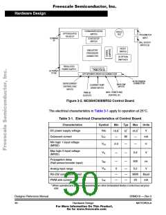
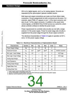
Table 3-2. Electrical Characteristics of Power Stage
Characteristics
DC input voltage
Symbol
Vdc
Min
140
100
—
Typ
160
208
70
Max
230
240
—
Units
V
AC input voltage
Vac
V
I
Quiescent current
mA
CC
V
Min logic 1 input voltage
Max logic 0 input voltage
Input resistance
2.0
—
—
0
—
—
—
0.8
—
V
V
IH
V
IL
R
10 kΩ
—
In
V
Analog output range
Bus current sense voltage
Bus voltage sense voltage
Peak output current
3.3
—
V
Out
I
—
—
—
563
8.09
—
mV/A
mV/V
A
Sense
V
—
Bus
I
2.8
PK
Brake resistor dissipation
(continuous)
P
—
—
50
W
BK
Brake resistor dissipation
(15 sec pk)
P
—
—
—
—
100
85
W
W
BK(Pk)
P
Total power dissipation
diss
3.5 Optoisolation Board
Motorola’s embedded motion control series optoisolation board links
signals from a controller to a high-voltage power stage. The board
isolates the controller, and peripherals that may be attached to the
controller, from dangerous voltages that are present on the power stage.
The optoisolation board’s galvanic isolation barrier also isolates control
signals from high noise in the power stage and provides a noise-robust
systems architecture.
Signal translation is virtually one-for-one. Gate drive signals are passed
from controller to power stage via high-speed, high dV/dt, digital
optocouplers. Analog feedback signals are passed back through
HCNR201 high-linearity analog optocouplers. Delay times are typically
DRM019 — Rev 0
MOTOROLA
Designer Reference Manual
Hardware Design
33
For More Information On This Product,
Go to: www.freescale.com

 ETC [ ETC ]