Freescale Semiconductor, Inc.
Hardware Design
FORWARD/REVERSE
SPEED
POT
OPTOISOLATED
RS-232 I/F
SWITCH
TACHOMETER
INPUT
TERMINAL
I/F
START/STOP
SWITCH
HALL EFFECT
INPUTS (3)
RESET
EMULATOR/
PROCESSOR
CONNECTOR
SWITCH
(2) OPTION
SWITCHES
REGULATED
POWER SUPPLY
PWM LEDs (6)
dc POWER
12 Vdc
OPTO/POWER DRIVER I/O CONNECTOR
40-PIN RIBBON
CONNECTOR
OVERCURRENT/
OVERVOLTAGE
INPUTS
BACK EMF
INPUTS
CURRENT/TEMP
SENSE INPUTS
MISC. POWER AND
CONTROL I/O
PWM (6)
OUTPUTS
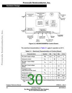
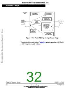
Figure 3-2. MC68HC908MR32 Control Board
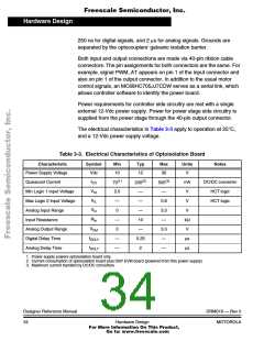
The electrical characteristics in Table 3-1 apply to operation at 25°C.
Table 3-1. Electrical Characteristics of Control Board
Characteristics
DC power supply voltage
Quiescent current
Symbol
Min
Typ
Max
Units
V
*
*
*
Vdc
10.8
12
16.5
I
—
80
—
—
mA
CC
Min logic 1 input voltage
(MR32)
V
2.0
—
—
0.8
500
V
V
IH
Max logic 0 input voltage
(MR32)
V
—
—
IL
Propagation delay
(Hall sensor/encoder input)
t
—
ns
dly
V
Analog input range
0
—
—
—
5.0
9600
20
V
In
RS-232 connection speed
PWM sink current
—
—
Baud
mA
I
PK
* When operated and powered separately from other Embedded Motion Control tool set prod-
ucts
Designer Reference Manual
30
DRM019 — Rev 0
Hardware Design
MOTOROLA
For More Information On This Product,
Go to: www.freescale.com

 ETC [ ETC ]