HY29F800
the duration of the RESET# pulse. The device also
resets the internal state machine to reading array
data. If an operation was interrupted by the as-
sertion of RESET#, it should be reinitiated once
the device is ready to accept another command
sequence to ensure data integrity.
device, enabling the system to read the boot-up
firmware from the Flash memory.
Sector Protect/Unprotect Operations
Hardware sector protection can be invoked to dis-
able program and erase operations in any single
sector or combination of sectors. This function is
typically used to protect data in the device from
unauthorized or accidental attempts to program
or erase the device while it is in the system (e.g.,
by a virus) and is implemented using program-
ming equipment. Sector unprotection re-enables
the program and erase operations in previously
protected sectors.
Current is reduced for the duration of the RESET#
pulse as described in the Standby Operation sec-
tion above.
If RESET# is asserted during a program or erase
operation, the RY/BY# pin remains Low (busy) until
the internal reset operation is complete, which re-
quires a time of tREADY (during Automatic Algo-
rithms). The system can thus monitor RY/BY# to
determine when the reset operation completes,
and can perform a read or write operation tRB after
RY/BY# goes High. If RESET# is asserted when
a program or erase operation is not executing (RY/
BY# pin is High), the reset operation is completed
within a time of tRP. In this case, the host can per-
form a read or write operation tRH after the RE-
SET# pin returns High .
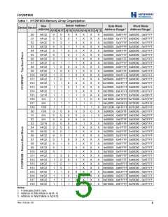
Table 1 identifies the nineteen sectors and the
address range that each covers. The device is
shipped with all sectors unprotected.
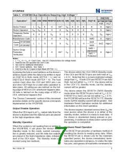
The sector protect/unprotect operations require a
high voltage (VID) on address pin A[9] and the CE#
and/or OE# control pins, as detailed in Table 3.
When implementing these operations, note that
VCC must be applied to the device before applying
The RESET# pin may be tied to the system reset
signal. Thus, a system reset would also reset the
VID, and that VID should be removed before remov-
ing VCC from the device.
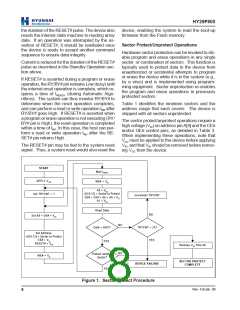
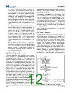
START
Wait tWPP1
APPLY V CC
WE# = VIH
A9 = VID
A[18:12] = Sector to Protect
OE# = CE# = A6 = A0 = V IL
A1 = VIH
Set TRYCNT = 1
Increment TRYCNT
Read Data
NO
Set A9 = OE# = V ID
NO
Data = 0x01?
TRYCNT = 25?
YES
Set Address:
A[18:12] = Sector to Protect
CE# = VIL
YES
RESET# = VIH
Remove VID from A9
NO
Protect Another
Sector?
WE# = VIL
SECTOR PROTECT
COMPLETE
DEVICE FAILURE
YES
Figure 1. Sector Protect Procedure
Rev. 4.0/Jan. 00
8

 ETC [ ETC ]