HALF-STEP/FULL-STEP
CONNECTION DIAGRAM
The AA2020A and AA2820 can operate a motor in half-step or full-step
operation. In half-step mode, the motor is stepped by alternately energizing
one phase, and then two phases of the motor. With a 1.8 degree motor (200
steps/rev), half-step mode will provide 400 steps/revolution. Table 2 below
shows the sequence for half-step.
VHV
VLV
Q5
Q1
Q3
PHASE 1
PHASE 2
PHASE 3
PHASE 4
+5V
+5V
1
1
0
0
0
0
0
1
0
1
1
1
0
0
0
0
0
0
0
1
1
1
0
0
0
0
0
0
0
1
1
1
C1
1
13
Vdd
Vdd
2
3
4
6
7
Vdd
OP
C/P
I/P
OUT 5
OUT 1
OUT 3
Rsense
VHV
21
22
CC
W
16
17
R13
R24
VLV
CLOCK
CCW
23
5
IN 1
IN 2
IN 3
IN 4
15
19
18
OUT 6
OUT 2
OUT 4
Q6
DIRECTION 20
HS/FS
8
+5V
+5V
+5V
11
10
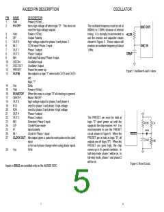
PRESET
ON/OFF
14
12
24
CW
ON/OFF
GND
OSC OUT
124
10K
49.9K
0.1uF
4.22K
220pF
GND
C2
9
OSC IN
Q2
Q4
AA2020A
Table 2: Half-step Phase Sequence 1=ON, 0=OFF
Rsense
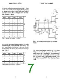
Figure 9: Typical hookup for unipolar bilevel step motor driver using
AA2020A.
In Full-step mode, there are always two phases on at a time. The motor is
stepped by turning off a phase and turning on the opposite phase (i.e. - turn
phase 1 off and turn phase 3 on). A standard 1.8 degree motor will provide
200 steps/revolution in full-step mode. The phase sequence for full-step is
shown in figure y2.
Figure 9 shows a typical hookup with the AA2020A chip. Q1-Q4 are npn
darlington transistors used for the 4 phase outputs. Q5 and Q6 are pnp
darlington transistors used as high-side switches. The Rsense resistors are
used to sense the current flowing through the motor. When the current in
phase 1 or 3 reaches a level set by the potentiometer, comparator C1 goes
low (logic "0") and resets (turns off) OUT5. The same thing happens for phase
2 and 4.
PHASE 1
PHASE 2
PHASE 3
PHASE 4
CC
W
1
0
0
1
1
1
0
0
0
1
1
0
0
0
1
1
CW
Table 3: Full-step Phase Sequence 1=ON, 0=OFF
11
12

 ETC [ ETC ]