CLOCK INPUT SELECTION
There are three three clocking methods for the AA2020A and AA2820. The
C/P input is used to select CLOCK inputs or PHASE inputs. The IP input is
used to select positive or negative going inputs. See Table 1.
INPUT CLOCK SELECTION
+ GOING CLOCK INPUTS
- GOING CLOCK INPUTS
C/P
1
IP
0
1
1
POSITIVE TRUE PHASE INPUTS
0
0
NEGATIVE TRUE PHASE INPUTS
0
1
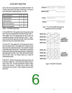
Figure 7: The CLOCK and DIRECTION signals are
equivalent to the CW and CCW signals
TABLE 1: CLOCK INPUT SELECTION.
CLOCK and DIRECTION: Pulses applied to the CLOCK input will cause the
motor to step in the clockwise direction if the DIRECTION input is logic "1".
Pulses applied to the CLOCK input will cause the motor to step in the
counterclockwise direction if the DIRECTION input is logic "0". Figure 7
shows Clock and Direction signals which will make 5 steps in the clockwise
direction and 5 steps in the counterclockwise direction.
CLOCK and CCW: Pulses applied to the CLOCK input cause the motor to
step in the clockwise direction. Pulses applied to the CCW input cause the
motor to step in the counterclockwise direction. Pulses should NOT be applied
to both of these inputs at the same time. The input which is not being used
should be held low when using positive going clock inputs, or held high when
using negative going clock inputs. Figure 7 shows Clock and Direction signals
which will make 5 steps in the clockwise direction and 5 stepsin the
counterclockwise direction.
PHASE INPUTS: Half-step or Full-step sequence phase inputs may be used
to synchronize multiple axes. Only the phase input sequences shown in
Figure 8 may be used. The phase input sequences in figure 4 produce
clockwise motor movement. The phases may be reversed to obtain
counterclockwise motor movement. Positive or Negative true phase inputs
may be used.
Figure 8: PHASE INPUT SEQUENCE
9
10

 ETC [ ETC ]