TYPICAL OUTPUT CHARACTERISTICS
BILEVEL DRIVE
The basic function of a step motor driver is to control the motor winding
currents. Motor performance is determined by how fast the driver can
increase and decrease the winding currents. A rapid rise in winding current is
achieved by applying a high voltage directly to a motor. This rapid rise of
current is also referred to as the "kick" or operating current. When a desired
current level is reached, a low voltage is applied to maintain a suitable holding
current level. When a motor winding is turned off, a rapid decrease in winding
current is achieved by routing the energy in the collapsing field back to the
power supply through a high voltage path. The high voltage supply furnishes
the energy necessary to maintain motor output torque at high step rates thus
providing high mechanical power output. The low voltage supply provides
much of the current needed at low step rates and all of the holding current.
(VOLTS)
The efficiency of bilevel drive makes for step motor performance that is far
superior to that produced by L/R drives. Also, bilevel drivers do not use high
frequency switching techniques as chopper drivers do. Consequently, they do
not create the EMI, RFI, and motor heating problems that are associated with
chopper drivers.
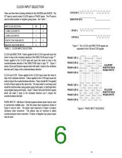
AA2020 Operation
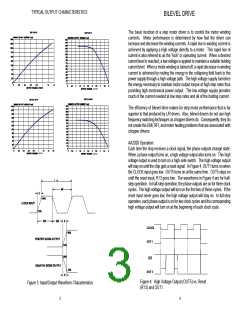
Each time the chip receives a clock signal, the phase outputs change state.
When a phase output turns on, a high voltage output also turns on. This high
voltage output is used to turn on a high-side switch. The high voltage output
will stay on until the chip gets a reset signal. In Figure 4, OUT1 turns on when
the CLOCK input goes low. OUT5 turns on at the same time. OUT5 stays on
until the reset input, R13 goes low. The waveforms in Figure 4 are for half-
step operation. In half-step operation, the phase outputs are on for three clock
cycles. The high voltage output will turn on the first two of these cycles. If the
reset input never goes low, the high voltage output will stay on. In full-step
operation, each phase output is on for two clock cycles and the corresponding
high voltage output will turn on at the beginning of each clock cycle.
(VOLTS)
(VOLTS)
Figure 4: High Voltage Output (OUT5) vs. Reset
(R13) and OUT1.
Figure 3: Input/Output Waveform Characteristics
3
4

 ETC [ ETC ]