Proprietary TranSwitch Corporation Information for use Solely by its Customers
L3M
TXC-03452B
DATA SHEET
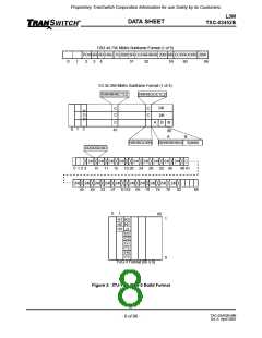
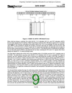
DS3 44.736 Mbit/s Subframe Format (1 of 9)
200I
POH 8R 8R RRC 5I
8R 8R CCRRRRRR 208I 8R 8R CCRROORS 208I
1
2
3
30 31
32
59 60
61
87
1
30
59
87
1
J1
B3
C2
G1
F2
H4
Z3
Z4
Z5
9
AU-3/STS-1 SPE Format (87 x 9)
Figure 4. SONET AU-3/STS-1 SPE Build Format
When Add bus timing is selected, the clock (ACLK), C1J1 indication (AC1J1), and SPE indication (ASPE)
become input signals from the Add bus. When Drop timing is selected, the L3M device supports DC1J1 pointer
movements on the Drop bus, and adjusts the pointer value in the TUG-3s accordingly. An active low Add indi-
cator (ADD) is also provided to indicate the location of all time slots that are added to the bus by the L3M
device (e.g., TUG-3 A, B or C). In TUG-3 mode, the VC-4 path overhead bytes are optionally sent as output to
the bus when control bit NOPOH (Address CA, Bit 5) is set to 0. The selected clock is monitored for operation,
and an odd parity signal (APAR) is calculated for the bus data, including the SPE and C1J1 signals when these
signals are outputs (i.e., in external timing mode).
The Drop Block supports the STM-1/STS-3 bus signaling rate of 19.44 MHz and the STS-1 signaling rate of
6.48 MHz. The Drop Block uses the clock (DCLK), C1J1 indication (DC1J1) and a separate DC1 signal if
required, and SPE indication (DSPE) from a Drop bus for determining the location of the Path Overhead J1
byte in the VC-4, the three J1 bytes in the three STS-1 SPEs in the STS-3 signal, and the single SPE for STS-1
operation. The C1 pulse is required, and is synchronous with the first C1 byte in the STM-1 Section Overhead
bytes, or in the STS-3 or STS-1 Transport Overhead Bytes. The C1 pulse provides a framing indication for
determining the location of the bytes corresponding to the TUG-3 or STS-1 selected, and is also used by the
desynchronizer as a frame reference. The C1 pulse can be present in the DC1J1 signal or provided as a sepa-
rate signal (DC1). The Drop SPE (DSPE) is active during the POH and payload byte times. The Drop Bus clock
and composite C1J1 signal are monitored for operation, and odd parity is calculated and compared against the
incoming parity bit.
The Decode Block contains the logic for performing pointer interpretation and tracking for the selected TUG-3
signal, removing the Path Overhead bytes and Overhead Communication bits, and detecting the E1 byte for an
upstream AIS detection. The E1 byte carries an AIS indication from an associated TranSwitch SOT-3 or SOT-1
device. The SOT-3 or SOT-1 generates an AIS signal in one E1 byte for TUG-3 mode, or in each of the three E1
bytes for the three STS-1s, when a loss of frame, loss of pointer, loss of signal, or line AIS is detected. This
indication is used by the L3M device to generate a Path RDI indication, and for generating a received DS3 or
E3 AIS. In place of the E1 byte AIS, the L3M device also supports an alarm indication provided on the ISTAT
and PAIS signal leads. The TUG-3 pointer is monitored for loss of pointer, New Data Flag, and Path AIS. Per-
formance counters are provided for monitoring pointer movements. All POH bytes are written into RAM loca-
tions and are also provided at the POH interface. The POH interface consists of an output data lead (RPOHD),
TXC-03452B-MB
Ed. 6, April 2001
- 9 of 96 -

 ETC [ ETC ]