Proprietary TranSwitch Corporation Information for use Solely by its Customers
L3M
TXC-03452B
DATA SHEET
144-Lead 208-Lead
QFP BGA
Lead No. Lead No.
Symbol
I/O/P
Type
Name/Function
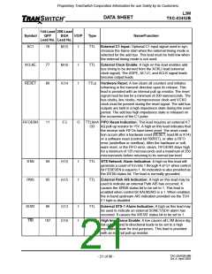
XC1
76
77
86
I
TTL
External C1 Input: Optional C1 input signal used to syn-
chronize the frame start when the external timing mode is
selected for the add bus. This lead must be held low when
the external timing mode is not used.
M15
M16
K14
XCLKE
RESET
I
I
TTL
External Clock Enable: A high on this lead enables add
bus timing to be derived from the XCKLI lead (external
clock signal). The ASPE, AC1J1, and ACLK signal leads
become output leads.
TTLp Hardware Reset: A low clears all counters and initiates
reframing in the transmit direction upon its release. This
lead is provided with an internal pull-up resistor. The reset
signal must be low for a minimum of 200 nanoseconds. The
bus clocks, line clocks, microprocessor clock and VCXO
clock must be present during the reset signal. The add bus
outputs are held in a high impedance state during the reset
period. The add bus high impedance state is released on
the occurrence of the C1 pulse.
FIFOERR
11
O
TTL8mA FIFO Reset Indication: This lead requires an external 4.7
F3
OD
kΩ pull-up resistor to +5V. A high on this lead indicates that
the receive side FIFOs have been reset. The reset condi-
tion occurs after a hardware reset (RESET, lead 86 or K14)
or a software reset (control bit RXRST), or after a FIFO
error (underflow or overflow). After the hardware or soft-
ware reset, or the FIFO error, clears, FIFOERR stays high
for a minimum of 125 microseconds and a maximum of 250
microseconds before returning to its normal low level.
STAI
PAIS
94
95
I
I
TTL
TTL
STS Network Alarm Indication: A high on this lead will
generate a count of 9 in bits 1 through 4 of G1 when control
bit FEBE9EN is equal to 1. An indication is also provided as
the XSTAI status bit. The lead is normally grounded.
H16
H15
External Path AIS Indication: A high on this lead may be
used to indicate an external Path AIS has occurred. It
causes the XPAIS status bit to be set to 1. This lead is
enabled when control bit XALM2AIS is a 1. When enabled,
the in-band upstream AIS indication provided via the TOH
E1 byte is disabled.
ISTAT
TRI
96
I
I
TTL
External STS-1 Alarm Indication: A high on this lead may
be used to indicate an external SONET/SDH alarm has
occurred. It causes the XISTAT status bit to be set to 1.
G13
D16
107
TTLp High Impedance Enable: A low causes all L3M device dig-
ital outputs and bi-directional leads to be set to a high
impedance state for test purposes. This lead is provided
with an internal pull-up resistor.
TXC-03452B-MB
Ed. 6, April 2001
- 21 of 96 -

 ETC [ ETC ]