Proprietary TranSwitch Corporation Information for use Solely by its Customers
L3M
TXC-03452B
DATA SHEET
ALARM INDICATION PORT
144-Lead 208-Lead
Symbol
QFP
BGA
I/O/P
Type
Name/Function
Lead No. Lead No.
RAIPD
28
O
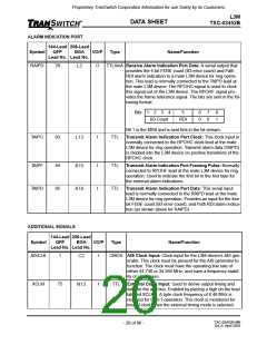
TTL4mA Receive Alarm Indication Port Data: A serial output that
provides the 4-bit FEBE count (B3 error count) and Path
RDI alarm indication to a mate L3M device for ring opera-
tion. This lead is normally connected to the TAIPD lead at
the mate L3M device. The RPOHC signal is used to clock
this signal out of the L3M device. The RPOHF signal pro-
vides the frame reference signal. The bits are sent in the fol-
lowing format:
L2
Bits
1
2
3
4
5
6
0
7
0
8
1
B3 Count
RDI
Bit 1 is the MSB and is sent first in the bit stream.
TAIPC
83
I
TTL
Transmit Alarm Indication Port Clock: This clock input is
normally connected to the RPOHC clock lead at the mate
L3M device for ring operation. Transmit alarm data (TAIPD)
is clocked into the L3M device on positive transitions of the
RPOHC clock.
L13
TAIPF
TAIPD
84
85
I
I
TTL
TTL
Transmit Alarm Indication Port Framing Pulse: Normally
connected to RPOHF lead at the mate L3M device for ring
operation. Used to indicate the first bit in the first byte for
the external alarm indications.
K15
K16
Transmit Alarm Indication Port Data: This serial input
lead is normally connected to the RAIPD lead at the mate
L3M device for ring operation. Provides an input for the four
bit FEBE count (B3 error count), and Path RDI alarm indica-
tion (as shown above for RAIPD).
ADDITIONAL SIGNALS
144-Lead 208-Lead
QFP BGA
Lead No. Lead No.
Symbol
I/O/P
Type
Name/Function
AISCLK
1
I
CMOS AIS Clock Input: Clock input for the L3M device’s AIS gen-
erator. This clock must be present for the AIS generator to
function. The clock must have the operating line rate of
either 44.736 or 34.368 MHz, and have a frequency stabil-
ity of +/- 20 ppm.
C2
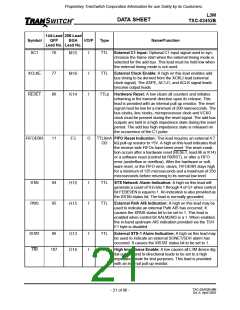
XCLKI
75
I
TTL
External Clock Input: Used to derive output timing and
data for the add bus. Enabled by placing a high on the lead
labeled XCLKE. A byte clock frequency of 6.48 MHz is
required for STS-1 operation. This clock is monitored for
loss of clock when the external timing mode is selected.
N13
TXC-03452B-MB
Ed. 6, April 2001
- 20 of 96 -

 ETC [ ETC ]