13.2.3
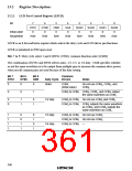
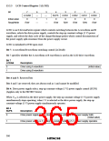
LCD Control Register 2 (LCR2)
Bit
7
LCDAB
0
6
—
1
5
—
1
4
SUPS
0
3
CDS3
0
2
CDS2
0
1
CDS1
0
0
CDS0
0
Initial value
Read/Write
R/W
—
—
R/W
R/W
R/W
R/W
R/W
LCR2 is an 8-bit read/write register which controls switching between the A waveform and B
waveform, selects the drive power supply, controls the step-up constant-voltage (5 V) power
supply, and selects the duty cycle of the charge/discharge pulses which control disconnection of
the power supply split-resistance from the power supply circuit.
LCR2 is initialized to H'60 upon reset.
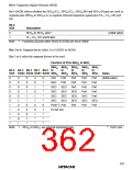
Bit 7: A waveform/B waveform switching control (LCDAB)
Bit 7 specifies whether the A waveform or B waveform is used as the LCD drive waveform.
Bit 7
LCDAB
Description
0
1
Drive using A waveform
Drive using B waveform
(initial value)
Bits 6 and 5: Reserved bits
Bits 6 and 5 are reserved; they are always read as 1 and cannot be modified.
Bit 4: Drive power supply select, step-up constant-voltage (5 V) power supply control (SUPS)
(Applies only to the H8/3887 Series)
When VCC is selected as the drive power supply, the step-up constant-voltage (5 V) power supply
simultaneously stops operating; when 5 V is selected as the drive power supply, the step-up
constant-voltage (5 V) power supply simultaneously operates.
Bit 4
SUPS
Description
0
Drive power supply is VCC, step-up constant-voltage (5 V) power supply halts
(Initial value)
1
Drive power supply is 5 V, step-up constant-voltage (5 V) power supply operates
350

 ETC [ ETC ]