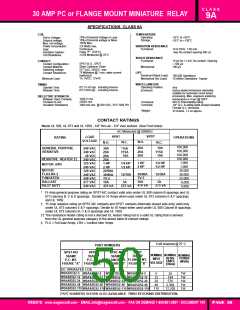
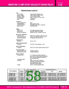
C L A S S
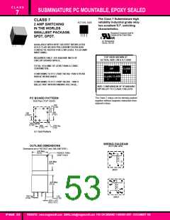
SUBMINIATURE PC MOUNTABLE, EPOXY SEALED
7
SPECIFICATIONS CLASS 7
COIL
Coil Voltages
TEMPERATURE
Pull-in Voltage:
80% of Nominal Voltage or less
10 % of Nominal Voltage or More
120% of nominal voltage, duty cycle: 100%.
327 Milliwatts max., min sensitivity: 200 milliwatts.
0.75 watts.
Operating:
-35˚C to +70˚C
Dropout:
Max. allowed coil voltage:
Nominal Power:
VIBRATION RESISTANCE
Functional:
15 g's, 10 to 2000 Hz,
No contact opening > 10 uS
Max. contact chatter
Max. coil dissipation
Coil Resistance range:
±10%
Destructive: 50 g'S.
CONTACTS
SHOCK RESISTANCE
Functional
Contact Configuration:
Contact Rating:
SPDT, DPDT
50g's 6mS half sine
Destructive: 150 g's.
SPDT: 50uA @ 50mV, 2A , 24VDC, 2A, 120VAC,
DPDT: 50uA @ 50mV, 2A, 24VDC, 0.6A,100VAC,
Gold Clad Silver Palladium.
Mechanical:
Contact Material:
Contact Resistance:
LIFE
Initial 50 mΩ
100 Milliohms max @ 6VDC 10 Milliamps.
Mechanical:
Electrical:
100 Million Operations
100,000 Operations- 2 Amp
24VDC,
1.0 AMP 120VAC (Rated Load).
TIMING
Operate Time:
Release Time:
4.0 mS Max. @ Nominal Voltage. Typ.
5.0 mS Max. @ Nominal Voltage. Typ
MISCELLANEOUS
Terminal Finish:
Terminals are solder Coated
and Epoxy free to provide excellent
solderability. Max. exposure to
soldering temperature is 5 seconds
@ 250˚C.
After cleaning process, pierce a
small hole in cover for venting.
Any
UL, 94V-O Plastic, Epoxy Sealed.
2.7 Grams . (.095 oz.)
DIELECTRIC STRENGTH
All Mutually Insulated Points: 500 VAC for 1 Minute, 1 Milliamp max.
leakage, or 600VAC for 1 Second, 1
Milliamp leakage.
Surge Test:
Meets FCC 68.302 ( 1500V Surge )
and 68.304 ( 1000V Dielectric ).
500 VDC Exceeds 1000 Megohms.
Mounting Position:
Enclosure:
Weight:
Insulation Resistance:
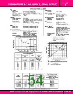
OPERATE/RELEASE TIME
4
3
2
1
After cleaning process, pierce
0.40 (1mm) hole in cover for
venting.
OPERATE TIME
COIL TEMPERATURE RISE
80˚
70˚
60˚
50˚
E2
Rt
RELEASE TIME
E2
0
R20
0.7
0.3
0.5
0.6
0.8
0.9
0.4
40˚
30˚
(WATTS)
COIL APPLIED POWER
R.F. PERFORMANCE
20˚
10˚
0
Frequency
Insertion Loss
(dB)
Isolation
(dB)
VSWR
Common to
N.O. or N.C.
Contacts
0.4
0.6 0 . 7 0.8
0.5
COIL POWER CONSUMPTION
0.1 0.2 0.3
Common to
N.O. or N.C.
Contacts
N.O. or N.C.
Contacts to
Coil
(MHz)
E2
Rt
E2
R20
COIL VOLTAGE
=
COIL RESIST. VALUE AFTER TEMP. WAS RAISED
65
50
42
35
31
29
28
0.05
0.10
0.30
0.50
0.60
0.65
0.75
1.03:1
1.04:1
1.05:1
1.06:1
1.07:1
1.08:1
1.10:1
10
50
COIL VOLTAGE
=
COIL RESIST. VALUE AT 20˚C
100
200
300
400
500
COIL - Measured at 25˚C
CROSS REFERENCE
Part
Numbers
Contact
Configuration
Nominal
Power
(mW)
Nominal
Input
Voltage
Nominal
Resis-
tance
COMMUNICATIONS
INSTRUMENTS INC / MIDTEX
(CII / MIDTEX)
(Ohms)
W7PCX-1
W7PCX-3
W7PCX-4
5 VDC
12 VDC
24 VDC
330
330
370
MMS105
MMS112
MMS124
SPDT
SPDT
SPDT
75
440
1550
W7PCX-5
W7PCX-7
W7PCX-8
5 VDC
12 VDC
24 VDC
330
330
370
MMS205
MMS212
MMS224
DPDT
DPDT
DPDT
75
440
1550
PART NUMBERS SHOWN ALSO AVAILABLE THRU STOCKING DISTRIBUTION.
WEBSITE: www.magnecraft.com EMAIL:info@magnecraft.com FAX ON DEMAND 1-800/891-2957 - DOCUMENT 100 PAGE 54

 ETC [ ETC ]