Si3210/Si3211/Si3212
PCM Interface
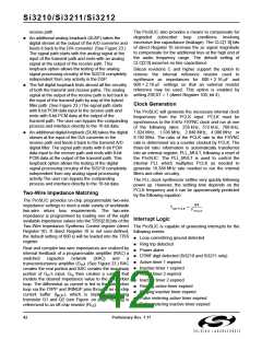
The ProSLIC contains a flexible programmable interface high impedance either on the negative edge of PCLK
for the transmission and reception of digital PCM during the LSB, or on the positive edge of PCLK
samples. PCM data transfer is controlled via the PCLK following the LSB. This is based on the setting of the
and FSYNC inputs as well as the PCM Mode Select TRI bit of the PCM Mode Select register. Tristating on
(direct Register 1), PCM Transmit Start Count (direct the negative edge allows the transmission of data by
registers 2 and 3), and PCM Receive Start Count (direct multiple sources in adjacent timeslots without the risk of
registers 4 and 5) registers. The interface can be driver contention. In addition to 8-bit data modes, there
configured to support from 4 to 128 8-bit timeslots in is a 16-bit mode provided. This mode can be activated
each frame. This corresponds to PCLK frequencies of via the PCMT bit of the PCM Mode Select register. GCI
256 kHz to 8.192 MHz in power of 2 increments. timing is also supported in which the duration of a data
(768 kHz and 1.536 MHz are also available.) Timeslots bit is two PCLK cycles. This mode is also activated via
for data transmission and reception are independently the PCM Mode Select register. Setting the TXS or RXS
configured using the TXS and RXS registers. By setting register greater than the number of PCLK cycles in a
the correct starting point of the data, the ProSLIC can sample period will stop data transmission because TXS
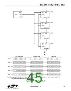
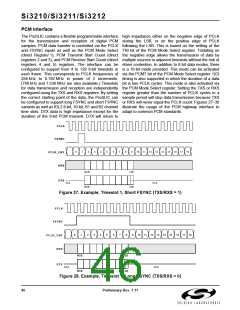
be configured to support long FSYNC and short FSYNC or RXS will never equal the PCLK count. Figures 27–30
variants as well as IDL2 8-bit, 10-bit, B1 and B2 channel illustrate the usage of the PCM highway interface to
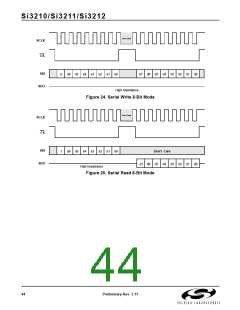
time slots. DTX data is high impedance except for the adapt to common PCM standards.
duration of the 8-bit PCM transmit. DTX will return to
PCLK
FSYNC
0
1
2
3
4
5
6
7
8
9
10
11
12
13
14
15
16
17
18
PCLK_CNT
DRX
MSB
MSB
LSB
LSB
DTX
HI-Z
HI-Z
Figure 27. Example, Timeslot 1, Short FSYNC (TXS/RXS = 1)
PCLK
FSYNC
PCLK_CNT
DRX
0
1
2
3
4
5
6
7
8
9
10
11
12
13
14
15
16
17
18
MSB
MSB
LSB
LSB
DTX
HI-Z
HI-Z
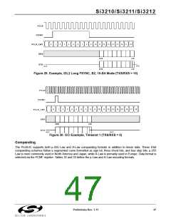
Figure 28. Example, Timeslot 1, Long FSYNC (TXS/RXS = 0)
46
Preliminary Rev. 1.11

 ETC [ ETC ]