Si3035
signalling, the master device will have a unique setting Register 13 must be 0.
relative to the slave devices. The DSP can use this
The receive path can support gains of 0, 3, 6, 9, and
information to determine which FSYNC marks the
beginning of a sequence of data transfers.
12 dB. The gain is selected by bits 2:0 (ARX2:ARX0).
The receive path can also be muted by setting bit 3
(RXM). The transmit path can support attenuations of 0,
3, 6, 9, and 12 dB. The attenuation is selected by bits
6:4 (ATX2:ATX0). The transmit path can also be muted
by setting bit 7 (TXM).
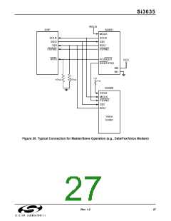
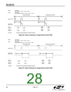
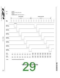
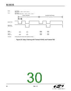
The delayed frame sync (FSD) of each device is
supplied as the FSYNC of each subsequent slave
device in the daisy chain. The master Si3035 will
generate an FSYNC signal for each device every 16 or
32 SCLK periods. The delay period is set by Register 14,
bit 2 (FSD). Figures 26–29 show the relative timing for
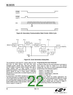
daisy chaining operation. Primary communication
frames occur in sequence, followed by secondary
Filter Selection
The Si3035 supports additional filter selections for the
receive and transmit signals. When set, the IIRE bit of
Register 16 enables the IIR filters defined in Table 12 on
page 11. This filter provides a much lower, however
non-linear, group delay than the default FIR filters.
communication
frames,
if
requested.
When
writing/reading the master device via a secondary frame,
all secondary frames of the slave devices must be
written as well. When writing/reading a slave device via
a secondary frame, the secondary frames of the master
and all other slaves must be written as well. "No
operation" writes/reads to secondary frames are
accomplished by writing/reading a zero value to address
zero.
If FSD is set for 16 SCLK periods between FSYNCs,
only serial mode 1 can be used. In addition, the slave
devices must delay the tri-state to active transition of
their SDO sufficiently from the rising edge of SCLK to
avoid bus contention.
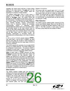
The Si3035 supports the operation of up to eight Si3035
devices on a single serial bus. The master Si3035 must
be configured in serial mode 1. The slave(s) Si3035 is
configured in serial mode 2. Figure 30 shows a typical
master/slave connection using three Si3035 devices.
When in serial mode 2, FSYNC becomes an input,
RGDT/FSD becomes the delay frame sync output, and
FC/RGDT becomes the ring detection output. In
addition, the internal PLLs are fixed to a multiply by 20.
This provides the desired sample rate when the master’s
SCLK is provided to the slave’s MCLK. The SCLK of the
slave is a no connect in this configuration. The delay
between FSYNC input and delayed frame sync output
(RGDT/FSD) will be 16 SCLK periods. The RGDT/FSD
output has a waveform identical to the FSYNC signal in
serial mode 0. In addition, the LSB of SDO is set to zero
by default for all devices in serial mode 2.
Gain Control
The Si3035 supports multiple gain and attenuation
settings for the receive and transmit paths, respectively,
via Register 13. When the ARX bit is set, 6 dB of gain is
applied to the receive path. When the ATX bit is set,
–3 dB of gain is applied to the transmit path.
Register 15 can be used to provide additional gain
control. For Register 15 to have an effect on the receive
and transmit paths, the ATX and ARX bits of
26
Rev. 1.2

 ETC [ ETC ]