Si3035
AOUT signal can be set to –20 dB, –26 dB, –32 dB, or An LCS value of zero means the loop current is less
mute. The receive portion of the AOUT signal can be than required for normal operation and the system
set to 0 dB, –6 dB, –12 dB, or mute. Figure 17 on page should be on-hook. Typically, an LCS value of 15 means
17 illustrates a recommended application circuit. In the the loop current is greater than 155 mA.
configuration shown, the LM386 provides a gain of
26 dB. Additional gain adjustments may be made by
current. This allows for a stable LCS value when the
varying the voltage divider created by R1 and R3 of
The LCS detector has a built-in hysteresis of 2 mA of
loop current is near a transition level. The LCS value is
a rough approximation of the loop current, and the
Figure 17.
designer is advised to use this value in a relative means
rather than an absolute value.
On-Hook Line Monitor
The Si3035 allows the user to detect line activity when
This feature enables the host processor to detect if an
the device is in an on-hook state. When the system is
additional line has “picked up” while the modem is
on-hook, the line data can be passed to the DSP across
transferring information. In the case of a second phone
the serial port while drawing a small amount of DC
going off-hook, the loop current falls approximately 50%
current from the line. This feature is similar to the
and is reflected in the value of the LCS bits.
passing of line information (such as caller ID), while
on-hook, following a ring signal detection. To activate
this feature, set the ONHM bit in Register 5.
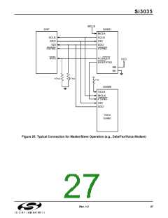
Multiple Device Support
The Si3035 supports the operation of up to seven
The on-hook line monitor can also be used to detect
whether a phone line is physically connected to the
Si3012 and associated circuitry. When the on-hook line
monitor is activated (if no line is connected), the output
of SDO will move towards a negative full scale value
(–32768). The value is guaranteed to be at least 89% of
negative full scale.
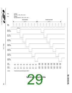
additional devices on a single serial interface. Figure 25
on page 27 shows the typical connection of the Si3035
and one additional serial voice codec (Si3000).
The Si3035 must be the master in this configuration. The
secondary codec should be configured as a slave device
with SCLK and FSYNC as inputs. On power up, the
Si3035 master will be unaware of the additional codec
on the serial bus. The FC/RGDT pin is an input,
operating as the hardware control for secondary frames.
The RGDT/FSD pin is an output, operating as the active
low ring detection signal. It is recommended that the
master device be programmed for master/slave mode
prior to enabling the ISOcap, because a ring signal
would cause a false transition to the slave device’s
FSYNC.
If a line is present while in on-hook line monitor mode,
SDO will have a near zero value. The designer must
allow for the group delay of the receive filter (12/Fs)
before making a decision.
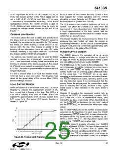
Loop Current Monitor
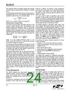
When the system is in an off-hook state, the LCS bits of
Register 12 indicate the approximate amount of DC
loop current that is flowing in the loop. The LCS is a
4-bit value ranging from zero to fifteen. Each unit
represents approximately 6 mA of loop current from
LCS codes 1–14. The typical LCS transfer function is
shown in Figure 24.
Register 14 provides the necessary control bits to
configure the Si3035 for master/slave operation. Bit 0
(DCE) sets the Si3035 in master/slave mode, also
referred to as daisy-chain mode. When the DCE bit is
set, the FC/RGDT pin becomes the ring detect output
and the RGDT/FSD pin becomes the frame sync delay
output.
Bits 7:5 (NSLV2:NSLV0) set the number of slaves to be
supported on the serial bus. For each slave, the Si3035
will generate a FSYNC to the DSP. In daisy-chain mode,
the polarity of the ring signal can be controlled by bit 1
(RPOL). When RPOL = 1, the ring detect signal (now
output on the FC/RGDT pin) is active high.
15
10
LCS
BIT
5
0
The Si3035 supports a variety of codecs (e.g., Si3000)
as well as additional Si3035s. The type of slave codec(s)
used is set by bits 4:3 (SSEL1:SSEL0). These bits
determine the type of signalling used in the LSB of SDO.
This assists the DSP in isolating which data stream is
the master and which is the slave. If the LSB is used for
0
6
12 18 24 30 36 42 48 54 60 66 72 78 84 90 96
Loop Current (mA)
155
Figure 24. Typical LCS Transfer Function
Rev. 1.2
25

 ETC [ ETC ]