7. The master generates another start condition.
8. The master repeats steps 2–7 to address the appropriate group and
write 1 or more data bytes.
9. The master terminates the cycle by issuing a stop condition.
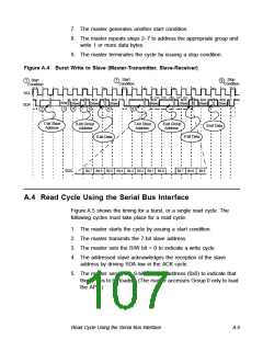
Figure A.4 Burst Write to Slave (Master-Transmitter, Slave-Receiver)
Start
Condition
Stop
Condition
Start
Condition
1
7
9
SCL
SDA
ACK
(Slave)
ACK
(Slave)
ACK
(Slave)
ACK
(Slave)
ACK
(Slave)
ACK
(Slave)
ACK
(Slave)
R/W
3
4
5
6
8
2
7-bit Slave
Address
8-bit Group
Address
7-bit Slave
Address
8-bit Group
Address
8-bit Data
8-bit Data
8-bit Data
SDA
Bit 7 Bit 6 Bit 5 Bit 4 Bit 3 Bit 2 Bit 1 Bit 0
Bit 7 Bit 6
Bit 5
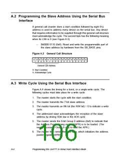
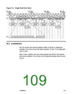
A.4 Read Cycle Using the Serial Bus Interface
Figure A.5 shows the timing for a burst, or a single read cycle. The
following cycles must take place for a read cycle:
1. The master starts the cycle by issuing a start condition.
2. The master transmits the 7-bit slave address.
3. The master sets the R/W bit = 0 to indicate a write cycle.
4. The addressed slave acknowledges the reception of the slave
address by driving SDA low in the ACK cycle.
5. The master sends the 8-bit Group 0 address (0x0) to indicate that
the APR is to be loaded. (The master accesses Group 0 only to load
the APR.)
Read Cycle Using the Serial Bus Interface
A-5

 ETC [ ETC ]