AN-32
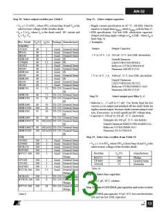
Step 30. Select output rectifier per Table 9
Step 31. Select output capacitor
• VR ≥ 1.25 xPIVS; where PIVS is from Step 28 and VR is the
rated reverse voltage of the rectifier diode.
• ID ≥ 3 x IO; where ID is the diode rated DC current and
IO = PO / VO.
• Ripple current specification at 105 °C, 100 kHz: Must be
equal to or larger than IRIPPLE, where IRIPPLE is from Step 27.
• ESR specification: Use low ESR, electrolytic capacitor.
Output switching ripple voltage is ISP x ESR , where ISP is
from Step 24.
Rec. Diode VR(V) ID(A) Package Manufacturer
• Examples:
Schottky
1N5819
SB140
Output
Output Capacitor
40
40
60
60
60
40
40
40
60
60
40
60
45
1
1
1
1
1.1
3
3
3
3
3
Axial General Semi
Axial General Semi
Axial General Semi
Axial IR
5 V to 24 V, 1 A 330 µF, 35 V, low ESR, electrolytic
SB160
MBR160
11DQ06
1N5822
SB340
MBR340
SB360
MBR360
SB540
SB560
UnitedChemicon
Axial IR
LXZ35VB331M10X16LL
Rubycon 35YXG330M10x16
Panasonic EEUFC1V331
Axial General Semi
Axial General Semi
Axial IR
Axial General Semi
Axial IR
Axial General Semi
Axial General Semi
TO-220 General Semi
IR
5 V to 24 V, 2 A 1000 µF, 35 V, low ESR, electrolytic
United Chemicon
5
5
7.5
LXZ35VB102M12X25LL
Rubycon 35YXG1000M12.5x25
Panasonic EEUFC1V102
MBR745
MBR760
MBR1045
60
45
7.5
10
TO-220 General Semi
TO-220 General Semi
IR
TO-220 General Semi
TO-220 General Semi
TO-220 General Semi
IR
Step 32.
Select output post filter L, C
• Inductor L: 2.2 µH to 4.7 µH. Use ferrite bead for low
current (≤1A) output and standard off-the-shelf choke for
highercurrentoutput. Increasechokecurrentratingorwire
size, if necessary, to avoid significant DC voltage drop.
• Capacitor C:100 µF to 330 µF, 35 V, electrolytic
MBR1060
MBR10100
MBR1645
60
100
45
10
10
16
MBR1660
60
16
TO-220 General Semi
Examples for 100 µF, 35 V, electrolytic:
MBR2045CT 45 20(2x10) TO-220 General Semi
United Chemicon KMG35VB101M6X11LL
Rubycon 35YXA100M6.3x11
IR
MBR2060CT 60 20(2x10) TO-220 General Semi
Panasonic ECA1VHG101
MBR20100
100 20(2x10) TO-220 General Semi
IR
Step 33. Select bias rectifier from Table 10
UFR
UF4002
UF4003
MUR120
EGP20D
100
200
200
200
1
1
1
2
2
Axial General Semi
Axial General Semi
Axial General Semi
Axial General Semi
Axial General Semi
Philips
Axial General Semi
Axial General Semi
Axial General Semi
Axial General Semi
Philips
TO-220 General Semi
TO-220 General Semi
Philips
TO-220 General Semi
Philips
• VR ≥ 1.25 xPIVB; where PIVB is from Step 28 and VR is the
rated reverse voltage of the rectifier diode.
Rectifier
VR (V)
Manufacturer
BYV27-200 200
BAV21
UF4003
1N4148
200
200
75
Philips
General Semi
Motorola
UF5401
UF5402
EGP30D
100
200
200
3
3
3
Table 10.
BYV28-200 200
3.5
Step 34. Select bias capacitor
MUR420 200
4
8
BYW29-200 200
BYV32-200 200
• Use 0.1 µF, 50 V, ceramic.
18
Step 35. SelectCONTROLpincapacitorandseriesresistor
• CONTROLpincapacitor:47µF,10V,lowcostelectrolytic
Table 9.
(Do not use low ESR capacitor).
B
12/02
13

 ETC [ ETC ]