AN-32
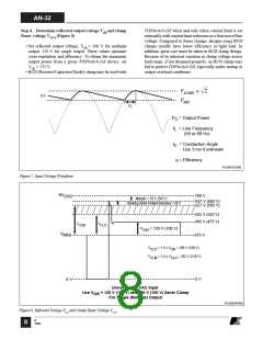
Step 9. Choose TOPSwitch-GXbased on AC input voltage,
VO, PO and η using AN-29 selection curves
KP
Input (VAC)
Continuous
Mode
Discontinuous
Mode
• ChoosethesmallestTOPSwitch-GXusingTOPSwitch-GX
Selection Curves in AN-29.
• Identify appropriate selection curves according to AC
input voltage and output voltage, VO.
• Continuous mode: Use selection curves as is.
• Discontinuous mode: Use selection curves with the output
power derated by 33%. This effectively makes a 10 W
discontinuous design equivalent to a 15 W continuous
design in TOPSwitch-GX selection.
Universal
230
0.4~1.0
0.6~1.0
≥1.0
≥1.0
Table 5
Step 6. Determine DMAX based on VMIN and VOR
• Switching Frequency fS: For DIP and SMP packages, set
fS = 132 kHz. For TO-220 package, choose between
66 kHz and 132 kHz.
• Continuous mode
VOR
DMAX
=
(VMIN − VDS ) + VOR
Step 10. Set ILIMIT reduction factor KI for External ILIMIT
• Discontinuous mode
external ILIMIT
•
where 0.3 ≤ KI ≤ 1.0
KI =
default ILIMIT
VOR
DMAX
=
• KI is set by the value of the resistor connected between M
pinandSOURCEpin(RefertoTOPSwitch-GXdatasheet).
• For applications demanding very high efficiency, a
TOPSwitch-GX bigger than necessary may be used by
lowering ILIMIT externally to take advantage of the lower
KP × (VMIN − VDS ) + VOR
• Set TOPSwitch-GX Drain to Source voltage, VDS = 10 V.
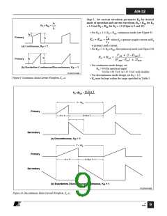
Step 7. Calculate primary peak current IP
• Continuous mode (KP ≤ 1.0)
RDS(ON)
.
• If no special requirement, set KI = 1.0.
• Calculate ILIMIT(min) and ILIMIT(max)
IAVG
IP =
ILIMIT(min) = default ⋅ILIMIT(min) ×KI
ILIMIT(max) = default ⋅ILIMIT(max) ×KI
K
P
1−
× DMAX
2
• Discontinuous mode (KP ≥ 1.0)
Step 11. Validate TOPSwitch-GX selection by checking IP
2 ×IAVG
IP =
against ILIMIT(min)
DMAX
• For KI = 1.0, check IP ≤ 0.96 x ILIMIT(min).
• For KI < 1.0, check IP ≤ 0.94 x ILIMIT(min).
• Choose larger TOPSwitch-GX if necessary.
PO
• Input average current
IAVG
=
η ×VMIN
Step 12. Calculate primary inductance LP
Step 8. Calculate primary RMS current IRMS
• Continuous mode
• Continuous mode
106 ×PO
Z × (1− η) + η
2
KP
LP =
×
2
K
IRMS = IP × DMAX
×
−KP+1
P
η
IP × KP × 1−
× fS (min)
3
2
where units are µH, watts, amps and Hz
• Discontinuous mode
IP2
• Discontinuous mode.
106 × PO
Z × (1− η) + η
IRMS = DMAX
×
3
LP =
×
2
1
η
IP × × fS (min)
2
where units are µH, watts, amps and Hz
B
12/02
10

 ETC [ ETC ]