AN-32
• Z is loss allocation factor and η is efficiency from Step 1.
Step 14. Set value for number of primary layers L and
number of secondary turns NS (may need iteration)
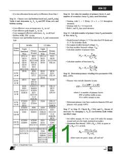
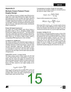
Step 13. Choose core and bobbin based on fS and PO using
Table 6 and determine Ae, Le, AL and BW from core and
bobbin catalog
• Starting with L = 2 (Keep 1.0 ≤ L ≤ 2.0 throughout
iteration).
• Starting with NS = 0.6 turn/volt.
• Both L and NS may need iteration.
• Core effective cross-sectional area, Ae: in cm2.
• Core effective path length, Le: in cm.
• Core ungapped effective inductance, AL: in nH/turn2.
• Bobbin width, BW: in mm.
Step 15. Calculatenumberof primaryturnsNP andnumber
of bias turns NB
• Choose core and bobbin based on fS, PO and construction
type.
• Diode forward voltages: 0.7 V for ultra-fast P/N diode and
0.5 V for Schottky diode.
• Set output rectifier forward voltage, VD.
• Set bias rectifier forward voltage, VDB.
• Calculate number of primary turns.
66 kHz
Triple
Insulated
Wire
132 kHz
Triple
Insulated
Wire
Output
Power
Margin
Wound
Margin
Wound
VOR
NP = NS ×
EF12.6
EE13
EF16
EE16
EE19
EI22
EI22
EE19
EI22/19/6 EF16
EEL16
EF20
EI25
EF12.6
EE13
EI22
EE19
E122/19/6
EEL16
VO + VD
• Calculate number of bias turns NB.
EE16
0-10 W
VB + VDB
NB = NS ×
EI22/19/6 EEL19
VO + VD
EF20
EI28
EEL22
EE19
EI22
EF20
EI25
10 W-
20 W
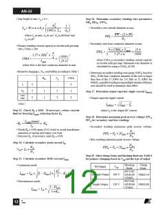
Step 16. DetermineprimarywindingwireparametersOD,
DIA, AWG
EF25 EI22/19/6 EEL19
EF20
EF25
EI30
EPC30
EEL25
E30/15/7
EER28
E128
• Primary wire outside diameter in mm.
20 W-
30 W
L × (BW − 2 × M)
EI28
EI30
EF25
EEL22
EF25
EI30
OD =
NP
E30/15/7 ETD29
EER28
30 W-
50 W
where L is number of primary layers,
BW is bobbin width in mm,
M is safety margin in mm.
EI35
EI33/29/
13-Z
EER28L
EF32
EPC30
ETD29
EI35
EF32
EI28
EI30
EEL25
E30/15/7
EER28
ETD29
EI35
EI33/29/
13-Z
EER28L
EF32
ETD34
EI40
• Determine primary wire bare conductor diameter DIA and
primary wire gauge AWG.
50 W-
70 W
ETD34
ETD34
EI40
Step 17 to Step 22. Check BM, CMA and Lg. Iterate if
necessary by changing L, NS or core/bobbin until within
specified range
E36/18/11 E36/18/11 E30/15/7
EI40
EER35
EER28
ETD29
70 W-
100 W
• Set safety margin, M. Use 3 mm (118 mils) for margin
wound and zero for triple insulated secondary.
• Maximum flux density: 3000 ≥ BM ≥ 2000, in gauss or
0.3 ≥ BM ≥ 0.2, in tesla.
ETD39
EER40
ETD39
EER40
EI35
EF32
100 W-
150 W
E42/21/15 ETD34 E36/18/11
EER35
E42/21/15 E42/21/20 E36/18/11 ETD39
E42/21/20 E55/28/21 EI40 EER40
100 × IP ×LP
BM =
E55/28/21
ETD39 E42/21/15
EER40 E42/21/20
E42/21/15 E55/28/21
E42/21/20
NP ×Ae
>150W
where units are gauss, amps, µH and cm2
E55/28/21
Table 6. Transformer Core.
B
12/02
11

 ETC [ ETC ]