ZENTRUM MIKROELEKTRONIK DRESDEN AG
“ASI for you” IC
Datasheet
As mentioned above, Pin LED2 is deactivated in Normal - Standard Status Indication Mode (Extended_Sta-
tus_Indication = ‘0’ and Dual_LED_Mode = ‘0’) for downward compatibility. In this case, the green LED shall be
connected directly to pin UOUT or different sensor supply.
3.9.2 Communication via Addressing Channel
As soon as the Addressing Channel becomes activated for telegram communication (see chapter
3.3 Addressing Channel Input IRD on page 22), LED1 is operated as Addressing Channel output port. This out-
put mode takes precedence over any status indication at LED1. If the Dual_LED_Mode flag is set, LED2 is
switched inactive (high impedance) while the Addressing Channel is active. This is to avoid interference to the
data communication by mixed optical signals.
3.9.3 Master-, Repeater-, Monitor Mode
In Master-, Repeater- and Monitor Mode LED1 provides the Manchester-II-coded, re-synchronized equivalent of
the telegram signal received at the AS-i input channel. The polarity of the Manchester-II-coded bit stream de-
pends on the values of the Pins DI2 and DI3.
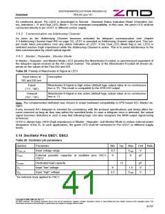
Table 28: Polarity of Manchester-II-Signal at LED1
Input values at
Description
DI2 and DI3 are:
Equal
(“11”, “00”)
Manchester-II-Signal is high active (default logic output value at no communica-
tion is ‘0’). This mode is compatible to the A²SI LED output
Unequal
(“01”, “10”)
Manchester-II-Signal is low active (default logic output value at no communica-
tion is ‘1’).
Note: The complemented definition was chosen to retain backward compatibility to A²SI based AS-i Master de-
signs.
Every received AS-i telegram is checked for consistency with the protocol specifications and timing jitters be-
come removed as long as they stay within the specified limits. In case a telegram error is detected, the output
signal becomes disturbed in such a way that following logic can also recognize the MAN output signal being
erroneous.
LED2 is always logic HIGH (high impedance) in Master-, Repeater- and Monitor Mode to reduce internal power
dissipation of the IC. In such applications, the green LED shall be connected to Pin UOUT or different supply
levels.
3.10 Oscillator Pins OSC1, OSC2
Table 29: Oscillator pin parameters
Symbol
VOSC_IN
COSC
Parameter
Min Typ. Max
Unit Note
Input voltage range
-0.3
0
VU5R
8
V
External parasitic capacitor at oscillator pins OSC1,
OSC2
pF
CLOAD
VIL
Dedicated load capacity
Input ”low” voltage
12
pF
1
0
1.5
V
1
VIH
Input ”high” voltage
3.5
VU5R
V
1 for external clock applied to OSC1
Copyright © 2006, ZMD AG, Rev.1.4
All rights reserved. The material contained herein may not be reproduced, adapted, merged, translated, stored, or used without the prior written consent of the copyright owner. The
Information furnished in this publication is preliminary and subject to changes without notice.
41/57

 ZMD [ Zentrum Mikroelektronik Dresden AG ]