ZENTRUM MIKROELEKTRONIK DRESDEN AG
“ASI for you” IC
Datasheet
3.9 LED outputs
3.9.1 Slave Mode
The ASI4U provides two LED pins for enhanced status indication. LED1 and LED2 both contain NMOS open
drain output drivers. In addition, LED2 contains a high voltage high impedance input stage for purposes of the
IC production test.
For compatibility to A²SI board layouts, where pin number 23 (former U5RD) had to be connected to U5R, the
LED2 function is turned OFF by default, keeping LED2 always at high impedance state. This is to protect LED2
against shorting the 5V supply (U5R) to ground. LED2 will be activated if the Enhanced_Status_Indication flag
and/or the Dual_LED_Mode flag are set in the E²PROM.
In order to comply with the signaling schemes defined in the AS-i Complete Specification a red LED shall be
connected to LED1 and a green LED shall be connected to LED2. Direct operation of a Dual LED is also sup-
ported but requires the Dual_LED_Mode flag to be set. This is because LED1 and LED2 need to be controlled
differently for AS-i compliant Dual LED signaling.
Following status indication is supported
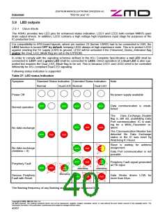
Table 27: LED status indication
Symptom
Standard Status Indication Extended Status Indication
Note
Normal
Dual LED Normal
Dual LED
gree
gree
gree
gree
red
red
red
red
Power Off
No power supply available
green
green
green
green
Data communication is estab-
lished
Normal operation
The
Data_Exchange_Disable
flag is still set, prohibiting Data
Port communication. IC is wait-
ing for a Write_Parameter re-
quest.
green
red
red
No data exchange
The Communication Monitor has
detected No Data Exchange
status or the IC was reset by
Watchdog IC Reset.
green
red
red
Slave is waiting for address
assignment.
yellow
red
green
green
No data exchange
(Address = 0)
red
red
Data Port communication is not
possible.
red/
Periphery Fault signal generated
at FID input.
green
Periphery Fault
red/
green
red
alternating
alternating
red
green
alternating
Serious Periphery
Fault with Reset
Data Strobe driven LOW for
more than 44µs.
green
red
The flashing frequency of any flashing status indication is around 2 Hz.
Copyright © 2006, ZMD AG, Rev.1.4
All rights reserved. The material contained herein may not be reproduced, adapted, merged, translated, stored, or used without the prior written consent of the copyright owner. The
Information furnished in this publication is preliminary and subject to changes without notice.
40/57

 ZMD [ Zentrum Mikroelektronik Dresden AG ]