ZENTRUM MIKROELEKTRONIK DRESDEN AG
“ASI for you” IC
Datasheet
3.11 IC Reset
Any IC reset turns the Data Output and Parameter Output Registers to 0xF and forces the corresponding output
drivers to high impedance state. Except at Power On Reset, Data Strobe and Parameter Strobe signals are
simultaneously generated to visualize possibly changed output data to external circuitry.
The Data_Exchange_Disable flag becomes set during IC reset, prohibiting any data port activity right after IC
initialization and as long as the external circuitry was not pre-conditioned by decent parameter output data.
Consequently the AS-i master has to send a Write_Parameter call in advance of the first Data_Exchange re-
quest to an initialized slave. Following IC initialization times apply:
Table 30: IC Initialization times
Symbol Parameter
Min
Max
2
Unit
ms
Note
1
tINIT
Initialization time after Software Reset (generated by master
calls Reset_Slave or Broadcast_Reset) or external reset via
DSR
2
3
tINIT2
tINIT3
Initialization time after power on
30
ms
ms
Initialization time after power on with high capacitive load
1000
1 guaranteed by design
2 ‘power on’ starts latest at VUIN = 18V, external capacitor at pin UOUT less than or equal 10µF
3 CUOUT = 470µF, tINIT3 is guaranteed by design only
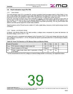
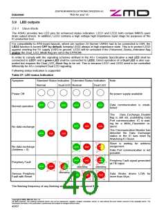
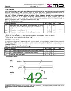
3.11.1 Power On Reset
In order to force the IC into a defined state after power up and to avoid uncontrolled switching of the digital logic
if the 5V supply (U5R) breaks down below a certain minimum level, a Power On Reset is executed under the
following conditions:
Table 31: Power On Reset Threshold Voltages
Symbol Parameter
Min
1.2
3.5
4
Max
1.7
4.3
6
Unit
V
Note
1
VPOR1F VU5R voltage to trigger internal reset procedure, falling voltage
VPOR1R VU5R voltage to trigger INIT procedure, rising voltage
1
V
tLow
Power-on reset pulse width
µs
1 guaranteed by design
UIN
about 15V
U5R
VPOR1R
VPOR1R
tLOW
reset
Figure 17: Power-On Behavior (all modes)
Copyright © 2006, ZMD AG, Rev.1.4
All rights reserved. The material contained herein may not be reproduced, adapted, merged, translated, stored, or used without the prior written consent of the copyright owner. The
Information furnished in this publication is preliminary and subject to changes without notice.
42/57

 ZMD [ Zentrum Mikroelektronik Dresden AG ]