Z8018x Family
MPU User Manual
291
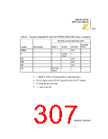
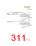
Table 56. Pin Status During RESET and LOW POWER OPERATION Modes (Continued)
Pin Status in Each Operation Mode
SYSTEM
Symbol
Pin Function
RESET
SLEEP
IOSTOP
STOP
MREQ
E
—
—
1
0
1
OUT
1
E Clock
Output
¬
¬
M1
WR
RD
Phi
—
—
—
—
1
1
1
1
1
1
¬
OUT
OUT
OUT
¬
1
1
1
¬
Phi Clock
Output
•
•
•
•
1: HIGH 0: LOW A: Programmable Z: High Impedance
IN (A): Input (Active) IN (N): Input (Not active) OUT: Output
H: Holds the previous state
¬ : same as the left
UM005001-ZMP0400

 ZILOG [ ZILOG, INC. ]