eZ80L92 MCU
Product Specification
164
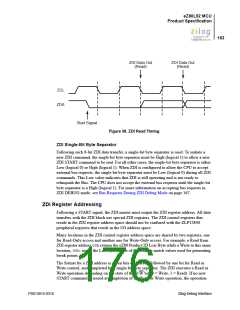
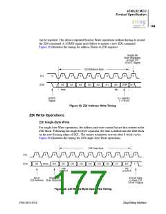
can be repeated. This allows repeated Read or Write operations without having to resend
the ZDI command. A START signal must follow to initiate a new ZDI command.
Figure 39 illustrates the timing for address Writes to ZDI registers.
Single-Bit
Byte Separator
or new ZDI
START Signal
ZDI Address Byte
ZCL
ZDA
S
1
2
3
4
5
6
7
8
9
A6
A5
A4
A3
A2
A1
A0
lsb
R/W 0/1
msb
START
Signal
0 = WRITE
1 = READ
Figure 39. ZDI Address Write Timing
ZDI Write Operations
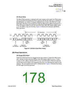
ZDI Single-Byte Write
For single-byte Write operations, the address and write control bit are first written to the
ZDI block. Following the single-bit byte separator, the data is shifted into the ZDI block
on the next 8 rising edges of ZCL. The master terminates activity after 8 clock cycles.
Figure 40 illustrates the timing for ZDI single-byte Write operations.
ZDI Data Byte
ZCL
ZDA
7
8
9
1
2
3
4
5
6
7
8
9
A0
Write
0/1
D7
D6
D5
D4
D3
D2
D1
D0
1
msb
of DATA
lsb
of DATA
lsb of
Single-Bit
End of Data
or New ZDI
START Signal
ZDI Address Byte Separator
Figure 40. ZDI Single-Byte Data Write Timing
PS013015-0316
Zilog Debug Interface

 ZILOG [ ZILOG, INC. ]