eZ80L92 MCU
Product Specification
163
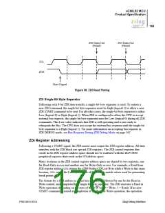
ZDI Data Out
(Read)
ZDI Data Out
(Read)
ZCL
ZDA
Start Signal
Figure 38. ZDI Read Timing
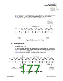
ZDI Single-Bit Byte Separator
Following each 8-bit ZDI data transfer, a single-bit byte separator is used. To initiate a
new ZDI command, the single-bit byte separator must be High (logical 1) to allow a new
ZDI START command to be sent. For all other cases, the single-bit byte separator is either
Low (logical 0) or High (logical 1). When ZDI is configured to allow the CPU to accept
external bus requests, the single-bit byte separator must be Low (logical 0) during all ZDI
commands. This Low value indicates that ZDI is still operating and is not ready to
relinquish the Bus. The CPU does not accept the external bus requests until the single-bit
byte separator is a High (logical 1). For more information on accepting bus requests in
ZDI DEBUG mode, see Bus Requests During ZDI Debug Mode on page 167.
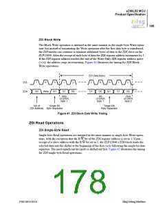
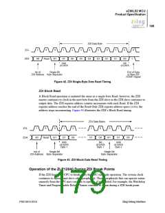
ZDI Register Addressing
Following a START signal, the ZDI master must output the ZDI register address. All data
transfers with the ZDI block use special ZDI registers. The ZDI control registers that
reside in the ZDI register address space should not be confused with the ZLP12840
peripheral registers that reside in the I/O address space.
Many locations in the ZDI control register address space are shared by two registers, one
for Read-Only access and another one for Write-Only access. For example, a Read from
ZDI register address 00h returns the eZ80 Product ID Low Byte while a Write to this same
location, 00h, stores the Low byte of one of the address match values used for generating
break points.
The format for a ZDI address is seven bits of address, followed by one bit for Read or
Write control, and completed by a single-bit byte separator. The ZDI executes a Read or
Write operation depending on the state of the R/W bit (0 = Write, 1 = Read). If no new
START command is issued at completion of the Read or Write operation, the operation
PS013015-0316
Zilog Debug Interface

 ZILOG [ ZILOG, INC. ]