MT312 MPEG Packet Data Output
9.3 MPEG/DSS Data Output Signals
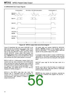
1st byte packet n
MCLKIV=1
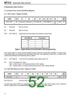
188 (DVB) or 130 (DSS) byte packet n
1st byte packet n+1
MOCLK
MDO7:0
MOSTRT
MOVAL
ERR_IND = 0
BKERR
ERR_IND = 1
BKERR
Ti
Tp
Figure 23 - MT312 output data wave form diagram
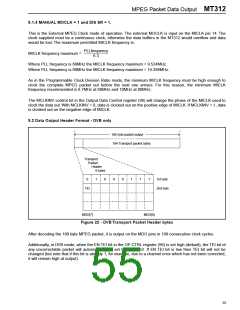
Figure 22 illustrates the case when ERR IND is set
high and the De-scrambler lock remains high. If the
first packet shown is good, BKERR would remain
high at the first MOSTRT shown, going low at the
second MOSTRT shown when that packet has
uncorrected block errors. If the first packet shown is
bad, BKERR will go low at the first MOSTRT shown
and continue low until a good packed is received.
All output data and signals (MDO[7:0], MOSTRT,
MOVAL, BKERR) change on the negative edge of
MOCLK (MCLKINV = 1) to present stable data and
signals on the positive edge of the clock.
A complete packet of data is output on MDO[7:0] on
188 (DVB) or 130 (DSS) consecutive clocks and the
MDO[7:0] pins will remain low during the inter packet
gaps.
MOCLK will be a continuously running clock once
symbol lock has been achieved in the QPSK block
and is derived from either the system clock or MICLK
if external clock is selected. MOCLK shown in Figure
24, Figure 25 and Figure 26 with MCLKINV = 1, the
default state, see register 96 in 7.1.3 FEC Set Up.
Register 97 (R/W) on page 51.
MOSTRT goes high for the first byte clock of a
packet.
MOVAL goes high on the first byte of a packet and
remains high until the 188th byte (DVB) or 130th byte
(DSS) has been clocked out.
MOCLK is the MPEG data byte rate clock, the
internal rate is calculated from the formulae in
section 9.4. The maximum movement in the packet
synchronisation byte position is limited to ± one
output clock period.
BKERR has two modes of operation, selected by
ERR IND bit 7 of MON CTRL register 103, see 59.
56

 ZARLINK [ ZARLINK SEMICONDUCTOR INC ]