MT312 Automatic Gain Control
8 Automatic Gain Control
8.1 Automatic Gain Control Read/Write Registers
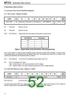
8.1.1 AGC Control. Register 39 (R/W)
Def
hex
NAME
ADR
B7
B6
B5
B4
B3
B2
B1
B0
AGC CTRL
39
Reserved Reserved
AGC SD[1:0]
AGC BW[2:0]
AGC
SL
R/W
26
B7:
Reserved.
Reserved.
AGC SD[1:0]
Must be set low.
Must be set low.
B6:
B5-4:
Sigma Delta clock decimation ratio related to system clock.
AGC SD[1:0]
Decimation
00
01
10
11
2
4
8
16
Table 4 - Sigma Delta clock decimation ratio programming
AGC control output is a pulse density modulated output created by a sigma-delta modulator. To reduce power
consumption this is not clocked at the full system clock rate. The frequency at which this is clocked is the
system clock divided by the decimation factor in Table 6.
B3-1:
B0:
AGC BW[2:0]
Front End AGC bandwidth (retain default value of 3).
AGC SL Analogue AGC slope
High = positive slope i.e. RF gain proportional to AGC voltage.
Low = negative slope i.e. RF gain inversely proportional to AGC voltage (default).
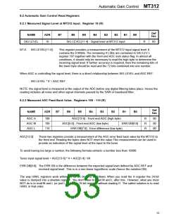
8.1.2 AGC REF Reference Value. Register 41 (R/W)
Def
hex
NAME
ADR
B7
B6
AGC REF[7:0] AGC reference level
Front End AGC reference value.
B5
B4
B3
B2
B1
B0
AGC REF
41
R/W
67
AGC REF[7:0]
The AGC loop control in MT312 is designed to bring the mean square value of the I signal (or the Q signal) at
the ADC output (prior to any digital filtering) to the value set by the AGC REF register.
52

 ZARLINK [ ZARLINK SEMICONDUCTOR INC ]