MT312 MPEG Packet Data Output
9 MPEG Packet Data Ouput
9.1 MPEG Clock Modes
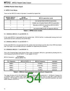
There are four MOCLK modes of operation, controlled by register bits.
MANUAL MOCLK
register 96 bit 7
DIS SR
register 97 bit 7
MOCLK generation mode
0
0
1
0
1
0
Use Symbol Rate for MOCLK generation.
Disable use of Symbol Rate for MOCLK generation.
Manually set MOCLK period from MOCLK RATIO
(reg. 33).
1
1
Use external MICLK (pin 14) signal for MOCLK.
Table 5 - MPEG clock modes
9.1.1 MANUAL MOCLK = 0 and DIS SR = 0.
In this mode MOCLK is generated from the symbol clock . MOCLK will be a continuously running clock once
symbol lock has been achieved in the QPSK block.
9.1.2 MANUAL MOCLK = 0 and DIS SR = 1.
In this mode MOCLK is not generated from the symbol clock but instead uses the data in the QPSK decimation
ratio. This mode is not normally used but is available for engineering test purposes.
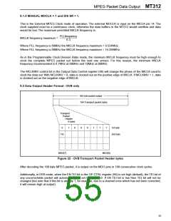
9.1.3 MANUAL MOCLK = 1 and DIS SR = 0.
This is the Programmable Clock Division Ratio mode of operation. MOCLK is generated by dividing the PLL
clock frequency by the MOCLK RATIO + 6 see register 33 on 47.
PLLfrequency
MOCLK frequency = ---------------------------------------------------
(MCLK_RATIO + 6)
PLL frequency
MOCLK RATIO + 6
MOCLK frequency
comment
60MHz
60MHz
90MHz
90MHz
6
9
6
9
10.0MHz
6.667 MHz
15MHz
maximum
minimum
maximum
minimum
10.0MHz
Table 6 - MOCLK input minimum and maximum frequencies
The range of values of 6 to 9 for (MOCLK RATIO + 6) will guarantee operation for 2 - 45 MSym/s. However, for
a restricted range of symbol rates, higher (MOCLK RATIO + 6) values may be used with a lower MOCLK
frequency. The equation in section 9.4 on 58 must be evaluated to ensure successful operation and avoid
buffer overflow in the MT312.
54

 ZARLINK [ ZARLINK SEMICONDUCTOR INC ]