Automatic Gain Control MT312
8.2 Automatic Gain Control Read Registers
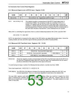
8.2.1 Measured Signal Level at MT312 Input. Register 19 (R)
Def
hex
NAME
ADR
B7
B6
B5
B4
B3
B2
B1
B0
SIG LEVEL
19
SIG LEVEL[11:4] - Signal level at MT312 input
R
00
B7-0:
SIG LEVEL[11:4]:
This register provides a measurement of the MT312 input signal level. It
contains the 8 MSBs. The remaining 4 LSBs are contained in SIG LEV L
register 107 together with the front end AGC lock status flag. In almost all
conditions, it should only be necessary to read the high byte to determine the
incoming signal level. If further accuracy is required, then the remaining bits of
the lower byte should be read and the 12 bits combined into one number.
When AGC is controlling the signal level, there is a direct relationship between SIG LEVEL and AGC REF:
SIG LEVEL * 8 = AGC REF
NOTE: the signal level is measured at the output of the ADC before any digital filtering takes place. Hence the
reading includes all noise and other signal channels passed by the SAW or baseband filter.
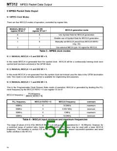
8.2.2 Measured AGC Feed Back Value. Registers 108 - 110 (R)
Def
hex
NAME
ADR
B7
B6
B5
B4
B3
B2
B1
B0
AGC H
AGC M
AGC L
108
109
110
AGC[13:6] - Front end AGC (high byte)
R
R
R
00
00
00
AGC[5:0] - Front end AGC (low byte)
ERR DB[9:8]
ERR DB[7:0] - Error difference (low byte)
AGC[13:0]:
These two registers provide a measurement of the AGC error feed back value by the MT312 to
the front end. Reading the bytes does NOT reset the value.This measurement can be used to
provide an indication of the signal level at the input to the tuner.
To avoid having too large a number, the following formula extracts a number less than 10000:
Tuner input signal level = AGC[13-6] * 4 + AGC[5-4] / 64.
ERR DB[9:0]: The ERR DB is the difference between the expected signal level defined by AGC REF and
received signal level. This is in a non-linear logarithmic scale (hence the notation DB).
The way H/M/L registers work within the QPSK block is as follows. When you read the H register the 24-bit
value is dumped into a shadow register. You don't have to read M and L after this. However, what you must
NOT do is to read M and L (or just L of a 24 or 16-bit register) without reading H. The safest solution is to read
H/M/L in that order.
53

 ZARLINK [ ZARLINK SEMICONDUCTOR INC ]