MT312 Forward Error Correction
B0:
BER tog High = BER toggle. This bit enables the audio signal output on the STATUS pin it indicates
BER during dish alignment, see 12, section 1.4.1.2. The frequency of the signal is controlled by
VIT MAXERR register (94), see 70.
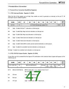
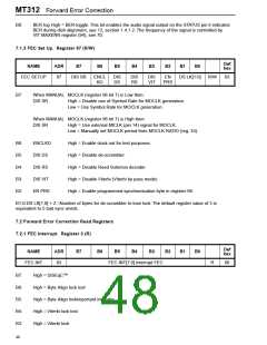
7.1.3 FEC Set Up. Register 97 (R/W)
Def
hex
NAME
ADR
B7
B6
B5
B4
B3
B2
B1
B0
FEC SETUP
97
DIS SR
ENCL
KO
DIS
DS
DIS
RS
DIS
VIT
EN
PRS
DS LK[1:0]
R/W
03
B7:
When MANUAL MOCLK (register 96 bit 7) is Low then:
DIS SR
High = Disable use of Symbol Rate for MOCLK generation.
Low = Use Symbol Rate for MOCLK generation.
When MANUAL MOCLK (register 96 bit 7) is High then:
DIS SR
High = Use external MICLK (pin 14) signal for MOCLK.
Low = Manually set MOCLK period from MOCLK RATIO (reg. 33).
High = Enable clock out for test purposes.
B6:
B5:
B4:
B3:
B2:
ENCLKO
DIS DS
DIS RS
DIS VIT
EN PRS
High = Disable de-scrambler.
High = Disable Reed Solomon decoder.
High = Disable Viterbi (Viterbi by pass mode)
High = Enable programmed synchronisation byte in register 98.
B1-0:DS LK[1:0] + 2 =Number of bytes for de-scrambler to lose lock. The default register value of 3 is
equivalent to 5 bad sync words.
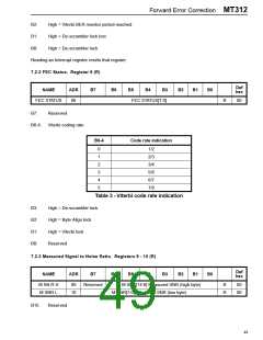
7.2 Forward Error Correction Read Registers
7.2.1 FEC Interrupt. Register 3 (R)
Def
hex
NAME
ADR
B7
B6
B5
B4
B3
B2
B1
B0
FEC INT
03
FEC INT[7:0] Interrupt FEC
R
00
B7:
B6:
B5:
B4:
B3:
High = DiSEqC™
High = Byte Align lock lost
High = Byte Align lockimportant indicator.
High = Viterbi lock lost
High = Viterbi lock
48

 ZARLINK [ ZARLINK SEMICONDUCTOR INC ]