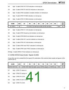
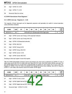
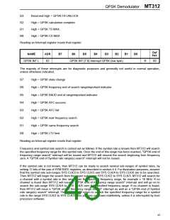
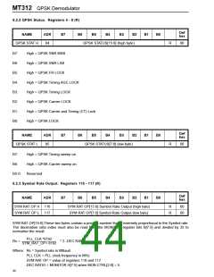
QPSK Demodulator MT312
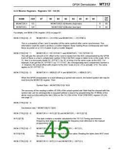
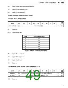
6.2.4 Monitor Registers. Registers 123 - 124 (R)
Def
hex
NAME
ADR
B7
B6
B5
B4
B3
B2
B1
B0
MONITOR H
MONITOR L
123
124
MONITOR[15:8] Monitor (high byte)
MONITOR[7:0] Monitor (low byte)
R
R
00
00
For details, see MON CTRL register (103) on page 62.
MON CTRL[3:0] = 0: MONITOR H = CS SYM I and MONITOR L = CS SYM Q.
This is a snapshot of two I and Q samples (of the same symbol) after carrier synchroniser. This
information could be used to produce a scatter diagram. Keep reading these continuously and mark
these as points on a 2-D I-Q plane to get a scatter diagram.
MON CTRL[3:0] = 1:
MONITOR H = DC OFFSET I and MONITOR L = DC OFFSET Q.
This will give the amount of DC offset in the I and Q inputs from the ADC compensated by the QPSK.
Each of these is a two's complement number. If the 6-bit ADC range is taken to be in the scale -32 to
31, then it is necessary divide DC OFFSET I by 16, to bring it to the same scale as the ADC. For
example, if we get the DC OFFSET I as "11111101", the corresponding two's complement number is
-3. However, the actual offset with respect to the ADC scale of [-32, 31] is actually -3/16. The same
applies to DC OFFSET Q.
MON CTRL[3:0] = 3:
MONITOR H = MBAUD OP H and MONITOR L = MBAUD OP L.
When the QPSK demodulator is in lock following a symbol rate search, the locked symbol rate may be
read from the MONITOR register. Then:
Symbol Rate = MONITOR[15:0]/ 1024.
The accuracy of this reading is within ±0.25% of the actual symbol rate. Note that the channel with this
symbol rate can be subsequently re-acquired without a search by programming the 14 MSBs of the
above read-out (discarding the two LSBs) as the 14 LSBs of the 16-bit SYM RATE register (23,24),
see page 27.
MON CTRL[3:0] = 5:
Decimation ratio = MONITOR[15:13]/32.
MON CTRL[3:0] = 6:
MONITOR H = M FLD[7:0] and MONITOR L = M FLD[7:0].
M FLD[7:0]:
This byte contains a number calculated in the TS FLD Timing synchroniser
frequency lock detector and is used for frequency lock detection in the manual
programming mode.
MON CTRL[3:0] = 7:
M TLD[15:0]:
MONITOR H = M TLD H and MONITOR L = M TLD L.
Measurement of the Timing lock detector value. Reading the bytes does NOT reset
the value.
MON CTRL[3:0] = 8:
MONITOR H = M PLD H and MONITOR L = M PLD L.
45

 ZARLINK [ ZARLINK SEMICONDUCTOR INC ]