MT312 DiSEqC Control
This is the software (partial) reset for DISEQC2 module. If this is set to 1 in the DISEQC2 listen (or
receive) period, any listen operations will be aborted and DISEQC2 will wait until the end of the next
transmission to expect a reply.
Note that the host beginning the next DISEQC2 transmission will have a similar effect to writing bit 4.
B3:
Interrupt enable for bit B3 of DISEQC2 INT STAT register 118.
B2:
B1:
B0:
Interrupt enable for bit B2 of DISEQC2 INT STAT register 118.
Interrupt enable for bit B1 of DISEQC2 INT STAT register 118.
Interrupt enable for bit B0 of DISEQC2 INT STAT register 118.
Bits B0 and B3 are interrupt enables. These determine whether bits B0 to B3 of DISEQC2 INT (register 118,
see 33) have any impact on the pin IRQ 57 of the MT312.
Note that buffer overflow interrupt does not have an interrupt enable and hence this cannot be brought out to
the IRQ pin.
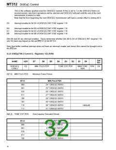
5.2.5 DiSEqCTM 2 Control 2. Registers 122 (R/W)
Def
hex
NAME
ADR
B7
B6
B5
B4
B3
B2
B1
B0
DISEQC2
CTRL2
122
MIN PULS PER
TONE EXT PER
MAX TONE R/W
PER
D4
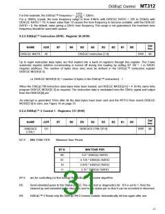
B[7:5]: MIN PULS PER
Minimum Pulse Period.
B7-5:
MIN PULS PER
000
001
010
011
100
101
110
111
24 * DISEQC RATIO
25 * DISEQC RATIO
26 * DISEQC RATIO
27 * DISEQC RATIO
28 * DISEQC RATIO
29 * DISEQC RATIO
30 * DISEQC RATIO
31 * DISEQC RATIO
(default)
B[4-2]: TONE EXT PER
Tone Impulse Extended Period.
B1-0:
TONE EXT PER
000
001
010
011
100
7 * DISEQC RATIO
8 * DISEQC RATIO
9 * DISEQC RATIO
10 * DISEQC RATIO
11 * DISEQC RATIO
32

 ZARLINK [ ZARLINK SEMICONDUCTOR INC ]