MT312 DiSEqC Control
B1:
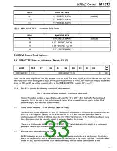
End of message interrupt (reset on read).
Bit B1 indicates a new message has been received. The end of a message is identified by a silent
period of about 6 ms following a byte. The end-of-message interrupt bit makes it easier for the host
processor to read DiSEqC™ data from MT312. Instead of reading a byte at a time, it can read the
message as a whole.
It is important to note that MT312 does not stop accepting bytes after setting end-of-message
interrupt. It will receive new messages, if any, whilst the current message is being read by the host.
Since 2-wire bus read rate is higher than the byte receive rate, there is no reason for FIFO buffer
overflow. After every received message there will be an interrupt.
B0:
End of byte interrupt (reset on read).
Bit B0 is set when a new byte is received. The host may wish to ignore byte interrupts and opt to read
received messages, as described below.
It is important to note that MT312 does not stop accepting bytes after setting end-of-message
interrupt. It will receive new messages, if any, whilst the current message is being read by the host.
Since 2-wire bus read rate is higher than the byte receive rate, there is no reason for FIFO buffer
overflow.
After every received message there will be an interrupt.
5.3.2 DiSEqC™M 2 Status Indicators. Register 119 (R)
Def
hex
NAME
ADR
B7
B6
B5
B4
B3
B2
B1
B0
DISEQC2 STAT 119
DISEQC2 STATUS[7:0]
R
00
B7-5:
B4-0:
DISEQC2 Finite State Machine State. This is primarily for debugging the device.
Silent period since last received bit, in multiples of 16 ms.
Bits B4-0 is reset to zero when a bit is received. When this 5-bit number reaches 176, the interrupt bit
B3 of DISEQC2 INT register is set. This is saturated to 31. Hence if the total period exceeds 496
ms this counter will continue to indicate 31.
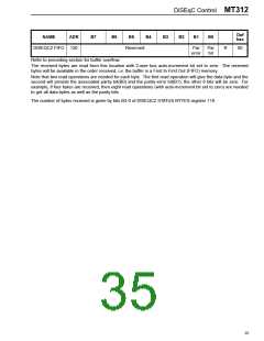
5.3.3 DiSEqC™ 2 FIFO. Register 120 (R)
Odd byte read of register 120:
Def
hex
NAME
DISEQC2 FIFO 120
Even byte read of register 120:
ADR
B7
B6
B5
B4
B3
B2
B1
B0
DISEQC2 FIFO[7:0]
R
00
This FIFO contains data bytes and parity bits collected. This can hold a maximum of 8 data bytes, 8 parity bits
and 8 parity error bits. The parity error bit is defined as the inverse of the exclusive-OR combination (or
modulo-2 addition) of all 9 bits (8 data and 1 parity). This bit will be zero when there is no parity error.
34

 ZARLINK [ ZARLINK SEMICONDUCTOR INC ]