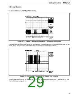
MT312 DiSEqC Control
5.2 DiSEqC Control Read/Write Registers
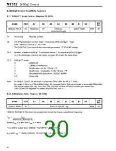
5.2.1 DiSEqC™ Mode Control. Register 22 (R/W)
Def
hex
NAME
ADR
B7
B6
B5
B4
B3
B2
B1
B0
DISEQC MODE
22
Reserved
HV
DISEQC
22kHz mode
R/W
00
instruction length
B7:
Reserved.
Must be set low.
B6:
HV H/V polarisation control: High = Horizontal, DISEQC[1] pin = high
Low = Vertical, DISEQC[1] pin = low
The DISEQC[1] pin controls the externally generated 13/18V LNB voltage.
B5-3:
B2-0:
Number of bytes in DiSEqC™ instruction minus 1, to output on DISEQC[0] pin.
i.e. if the message contains four bytes, program B5-3 with the value three.
DiSEqC™ mode:
0:
22kHz off
1:
22kHz on continuous
2:
Burst mode - on for 12.5ms = '0'
Burst mode - modulated 1:2 for 12.5ms = '1'
Modulated with bytes from DISEQC INSTR
Reserved.
3:
4:
5-7:
Note:
for modes 2 and 3, an interrupt is generated 16ms after the '0' or '1' burst.
for mode 4, there is a 16ms delay before the message bytes, then an interrupt is generated 16ms after
the last message byte has been sent. The requisite number of bytes must be pre-loaded into
DISEQC INSTR (register 36) before this bit is set, see 31.
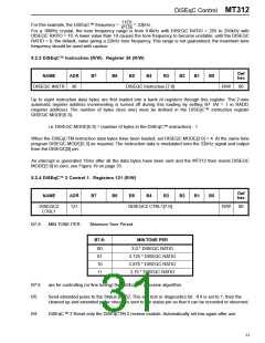
5.2.2 DiSEqC(tm) Ratio. Register 35 (R/W)
Def
hex
NAME
ADR
B7
B6
B5
B4
B3
B2
B1
B0
DISEQC RATIO
35
DISEQC RATIO[7:0]
R/W
00
DISEQC RATIO[7:0] This must be programmed to set the Diseqc output tone frequency.
F
=
F
out
xtal
4*DISEQC_RATIO[7:0]
Where F is in kHz and F
is in MHz.
xtal
out
For a 22kHz output tone, DISEQC RATIO[7:0] = 11.364 * F
xtal
e.g. with F
= 10MHz, DISEQC RATIO[7:0] = 114, or for 15 MHz 170.
xtal
30

 ZARLINK [ ZARLINK SEMICONDUCTOR INC ]