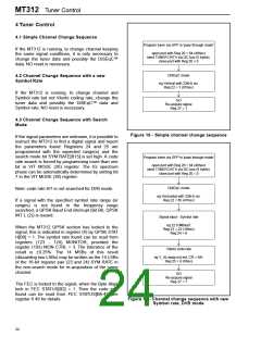
MT312 Tuner Control
Pin 45 = DATA2, this is a transparent, bi-directional connection to the primary DATA1.
Pin 44 = CLK2, this is a transparent, bi-directional connection to the primary CLK1.
If B6 = 0 then: GPP DIR[2:0] defines the input/output conditions of the GPP pins and:
If a pin[n] is defined as output then:
GPP PIN[n] high forces GPP[n] pin high
GPP PIN[n] low forces GPP[n] pin low
If a pin[n] is defined as input then:
GPP[n] pin high sets bit GPP PIN[n] high
GPP[n] pin low sets bit GPP PIN[n ] low
Allocation of GPP PIN[2:0] is:
GPP PIN[2] = DiSEqC™ v2.2 input, 3 wire bus Enable or can be used for any other application
GPP PIN[1] = DATA2 or 3 wire bus Data
GPP PIN[0] = CLK2 or 3 wire bus Clock
The register default state of 20 hex allows the GPP[2] pin to be used for the 3 wire bus Enable line and to be
kept low at all times, except when programming the Synthesiser.
When GPP[2] pin is used for DiSEqC™ v2.2 input, the GPP CTRL register will need to be set to zero after
every full reset to make GPP[2] an input.
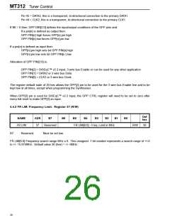
4.4.2 FR LIM: Frequency Limit. Register 37 (R/W)
Def
hex
NAME
ADR
B7
B6
B5
B4
B3
B2
B1
B0
FR LIM
37
Reserved
FR LIM[6:0] - Freq. Limit in MHz
R/W
30
B7:
Reserved.
Must be set low.
FR LIM[6:0] Frequency search range MHz x 8. This unsigned 7 bit number represents a search range of +/-0
to +/- 15.875MHz. Default value 30 (hex) = +/- 6MHz.
26

 ZARLINK [ ZARLINK SEMICONDUCTOR INC ]