Tuner Control MT312
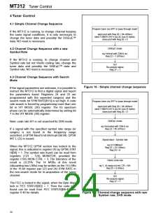
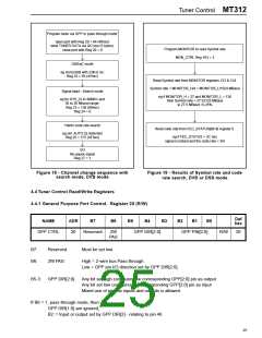
Program tuner via GPP in 'pass through mode'
open port with Reg 20 = 64 (40hex)
send TUNER DATA via I2C bus (5 bytes).
close port with Reg 20 = 0
Program MONITOR to read Symbol rate
MON_CTRL Reg 103 = 3
DiSEqC mode
eg Horizontal with 22kHz on:
Reg 22 = 65 (41hex)
Read Symbol rate from MONITOR registers 123 & 124.
Symbol rate = MONITOR_H/4 + MONITOR_L/1024 MBaud
Signal input - Search mode
eg if MONITOR_H = 27 and MONITOR_L = 136
then Symbol rate = 27.53125 MBaud
ie 27.5 MBaud ±0.25%
eg for SYS_CLK=60MHz and
30 to 20 Mbaud range:
Reg 23 = 136 (88hex)
Reg 24 = 0
Viterbi code rate search
Read code rate from FEC_STATUS[B6-4] register 6.
eg set: AUTO IQ detection
Reg 25 = 175 (AFhex)
eg if FEC_STATUS = 2C hex
signal is locked and the code rate = 3/4
GO
Re-aquire signal
Reg 27 = 1
Figure 18 - Channel change sequence with
search mode, DVB mode
Figure 19 - Results of Symbol rate and code
rate search, DVB or DSS mode
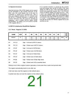
4.4 Tuner Control Read/Write Registers
4.4.1 General Purpose Port Control. Register 20 (R/W)
Def
hex
NAME
ADR
B7
B6
B5
B4
B3
B2
B1
B0
GPP CTRL
20
Reserved
2W
GPP DIR[2:0]
GPP PIN[2:0]
R/W
20
PAS
B7:
B6:
Reserved.
2W PAS:
Must be set low.
High = 2-wire bus Pass-through.
Low = GPP pin I/O direction set by GPP DIR[2:0].
B5-3:
GPP DIR[2:0]
Any bit set high configures the corresponding GPP[2:0] pin as output
Any bit set low configures the corresponding GPP[2:0] pin as input
Mixed use of pins as inputs and outputs is allowed.
If B6 = 1, pass-through mode, then:
GPP DIR[1:0] are ignored,
B2: = Input or output set by GPP DIR[2] - relating to pin 46.
25

 ZARLINK [ ZARLINK SEMICONDUCTOR INC ]