MA28138
Notes for Table 1:
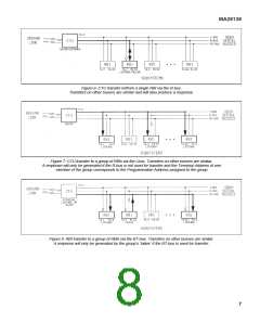
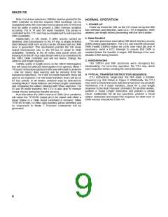
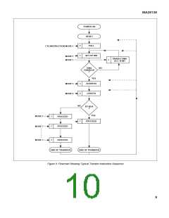
1. Interrogation bits 0:2 are the OBDH Sync pattern, bits 3:6 (Basic Addressing) or 3:5 (Extended Addressing) are BroadCast Pulses, bits 7:11 (Basic Addressing) or 6:11
(Extended Addressing) are the Terminal Address field, bits 12:14 are the Mode field, bits 15:30 are the Instruction field and bit 31 is the Parity bit.
2. An Interrogation containing validity, parity or length errors will not be decoded, will not hence be executed and will not cause a response to be generated. All unused
interrogations (i.e. those not listed above, subject to use of PA and BC in Extended Addressing mode as shown in Table 3) will similarly not be decoded, not be executed or
cause any response.
3. BroadCast Pulses (contained in Interrogation bits 3:6 (Basic Format) or Interrogation bits 3:5 (Extended Format)) are latched at the end of each Interrogation, regardless of
status; they can be externally qualified if desired. BCPVAL indicates the validity of the last Interrogation.
4. Specifying a new Programmed Address (PA) value of 0 causes no change. Specifying 63 causes the PA to be disabled. Other values cause the new PA to be loaded.
5. Specifying a new UCC value of 0 causes the UCC(0:6) output pins to be set to zero. Specifying 127 causes no change. Other values cause the new output value to be set.
6. ‘Input from l-bus’ means ‘write the word from the l-bus to the user at the current DMA address and respond with the new DMA length’; other bus selections should be
interpreted similarly.
7. Response bits 0:3 are the Destination Address field (always 0), bits 4:19 are the 16 bit Response Data field (bits 4:7 are ‘0’s for Length responses) and bit 20 is a Stop bit.
8. RBI/user status Response Data field format is: bus selection/direction (bits 4:6), user Service Request (SREQ) pin state (bit 7), Bi-Level status (BIL(0:5)) state (bits 8:13) and
PA value (bits 14:19).
9. Broadcast Polling is enabled if the (all ‘1’s) BroadCast address is used and Interrogation bits 29:30 match the pin-programmed Group Identifier inputs, Gl(0:1). The (single bit)
response is the state of the user Service Request (SREQ) pin; its position is controlled by the Poll Bit Position inputs, PBP(0:4)
10.The current DMA address is used for all Proceed instructions. Proceed instructions received after a DMA Overrun or DMA Error condition has been detected will not be
executed nor generate a response until a Read Status or a Reset DMA instruction has been executed. Responses are only generated for Proceed instructions which match
the TA.
11.In (IB or OB) BT-bus transfers, a status response is generated for the starting Proceed instruction only.
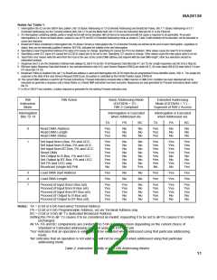
RBI
Instruction
Mode
RBI Action
Basic Addressing Mode
(EXTAEN = ‘0’) --
Extended Addressing
Mode (EXTAEN = ‘1’) --
Superset of RBI-2 Access
RBI-2 Compliant
Interrogation
Bits 12-14
Interrogation is Executed
when Addressed via:
Interrogation is Executed
when Addressed via:
TA
PA
BC
TA
PA
BC
0
1
Read DMA Address
Read DMA Length
Read DMA Status
Yes
Yes
Yes
No
No
No
No
No
No
Yes
Yes
Yes
No
No
No
No
No
No
Set Input from l-Bus, PA and UCC
Set Input from R-Bus, PA and UCC
Set Input from BT-Bus, PA and UCC
Reset DMA
Set Output to R-Bus, PA and UCC
Set Output tp BT-Bus, PA and UCC
Set PA and UCC only
Yes
Yes
Yes
Yes
Yes
Yes
Yes
No
No
No
No
No
No
No
No
No
No
No
No
No
No
No
No
Yes
Yes
Yes
Yes
Yes
Yes
Yes
Yes
No
Yes
Yes
Yes
Yes
No
No
Yes
No
Yes
Yes
Yes
Yes
No
No
Yes
Yes
Broadcast (single-bit) Poll
3
4
7
Load DMA start Address
Load DMA Length
Yes
Yes
No
No
No
No
Yes
Yes
Yes
Yes
Yes
Yes
Proceed (if Input from l-Bus set)
Proceed (if Input from R-Bus set)
Proceed (if Input from BT-Bus set)
Proceed (if Output to R-Bus set)
Proceed (if Output to BT-Bus set)
Yes
Yes
Yes
Yes
Yes
Yes
Yes
Yes
No
No
No
No
No
No
Yes
Yes
Yes
Yes
Yes
Yes
Yes
Yes
No
Yes
Yes
Yes
No
No
No
No
Notes: TA = (5 bit or 6 bit) hard-wired Terminal Address
PA = (5 bit or 6 bit) Programmable Address, set via Terminal Address only
BC = (5 bit or 6 bit) all-’1’s dedicated Broadcast Address
Setting the PA to all-’1’s causes it to be considered as invalid; requesting it to be set to all-’0’s causes it to remain
unchanged.
All TA, PA and BC comparisons are conducted to 5 bit or 6 bit precision depending on the current choice of
Standard or Extended addressing selected using the EXTFMT pin.
‘Yes’ indicates that an operation is valid and will be executed when addressed using that particular addressing
mode.
‘No’ indicates that an operation is not valid and will not be executed when addressed using that particular
addressing mode.
Table 2: Instruction Validity in both RBI Addressing Modes
11

 ZARLINK [ ZARLINK SEMICONDUCTOR INC ]