L9216B/H
Preliminary Data Sheet
September 2001
High-Voltage Ringing SLIC with Ground Start
Applications (continued)
Overhead Voltage (continued)
Ring Mode
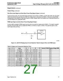
Supervision
The L9216 offers the loop closure and ring trip supervi-
sion functions. Internal to the device, the outputs of
these detectors are multiplexed into a single package
output, NSTAT. Additionally, a common-mode current
detector for tip or ring ground detection is included for
ground key applications.
In the ring mode, to maximize ringing loop length, the
overhead is decreased to the saturation of the tip ring
drive amplifiers, a nominal 4 V. The tip to ground volt-
age is 1 V, and the ring to VBAT1 voltage is 3 V.
Loop Closure
During the ring mode, to conserve power, the receive
input at RCVN/RCVP is deactivated. During the ring
mode, to conserve power, the AAC amplifier in the
transmit direction at VITR is deactivated. However, if
the AX amplifier at VTX is active during the ring mode,
differential ring current may be sensed at VTX during
the ring mode.
The loop closure has a fixed typical 10.5 mA on- to off-
hook threshold in the active mode and a fixed 11.5 mA
on- to off-hook threshold from the scan mode. In either
case, there is a 2 mA hysteresis with VCC = 5 V and a
1 mA hysteresis with VCC = 3.3 V.
Ring Trip
Loop Range
The ring trip detector requires only a single-pole filter at
the input, minimizing external components. An R/C
combination of 383 kΩ and 0.1 µF, for a filter pole at
5.15 Hz, is recommended.
The dc loop range is calculated using:
VBAT2 – VOH
--------------------------------------
RL =
– 2RP – RDC
ILIMIT
VBAT2 is typically applied under off-hook conditions for
power conservation and SLIC thermal considerations.
The L9216 is intended for short-loop applications and,
therefore, will always be in current limit during off-hook
conditions. However, note that the ringing loop length
rather than the dc loop length, will be the factor to
determine operating loop length.
The ring trip threshold is internally fixed as a function of
battery voltage and is given by:
RT (mA) = 67 * {(0.0045 * VBAT1) + 0.317}
where:
RT is ring trip current in mA.
VBAT1 is the magnitude of the ring battery in V.
There is a 6 mA to 8 mA hysteresis.
Battery Reversal Rate
The rate of battery reverse is controlled or ramped by
capacitors FB1 and FB2. Table 20 below shows FB1
and FB2 values vs. typical ramp time. Leave FB1 and
FB2 open if it is not desired to ramp the rate of battery
reversal.
Table 20. FB1 and FB2 Values vs. Typical Ramp
Time
CFB1 and CFB2
Transition Time
0.01 µF
0.1 µF
0.22 µF
0.47 µF
1.0 µF
1.22 µF
1.3 µF
1.4 µF
1.6 µF
20 ms
220 ms
440 ms
900 ms
1.8 s
2.25 s
2.5 s
2.7 s
3.2 s
Agere Systems Inc.
23

 ZARLINK [ ZARLINK SEMICONDUCTOR INC ]