L9216B/H
Preliminary Data Sheet
September 2001
High-Voltage Ringing SLIC with Ground Start
Table of Contents
Page Contents
Contents
Page
Introduction..................................................................1
Features....................................................................1
Applications...............................................................1
Description................................................................1
Features ......................................................................4
Description...................................................................4
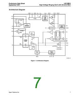
Architecture Diagram...................................................7
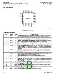
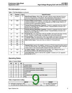
Pin Information ............................................................8
Operating States .........................................................9
State Definitions ........................................................10
Forward Active........................................................10
Reverse Active........................................................10
Scan........................................................................10
On-Hook Transmission—Forward Battery..............10
On-Hook Transmission—Reverse Battery..............10
Disconnect ..............................................................10
Ring.........................................................................10
Ground Start ...........................................................10
Thermal Shutdown..................................................11
Absolute Maximum Ratings (@ TA = 25 °C) ..............11
Electrical Characteristics ...........................................12
Test Configurations ...................................................19
Applications ...............................................................21
Power Control .........................................................21
dc Loop Current Limit..............................................22
Overhead Voltage...................................................22
Active Mode .........................................................22
Scan Mode ...........................................................22
On-Hook Transmission Mode...............................22
Ring Mode............................................................23
Loop Range ............................................................23
Battery Reversal Rate.............................................23
Supervision................................................................23
Loop Closure...........................................................23
Ring Trip .................................................................23
Tip or Ring Ground Detector...................................24
Power Ring .............................................................24
Sine Wave Input Signal and Sine Wave
ac Applications ......................................................... 31
ac Parameters........................................................ 31
Codec Types.......................................................... 31
First-Generation Codecs ..................................... 31
Third-Generation Codecs.................................... 31
ac Interface Network .............................................. 31
Design Examples................................................... 33
First-Generation Codec ac Interface
Network—Resistive Termination ...................... 33
Example 1, Real Termination.............................. 33
First-Generation Codec ac Interface
Network—Complex Termination....................... 36
Complex Termination Impedance Design
Example............................................................ 36
ac Interface Using First-Generation Codec......... 36
Transmit Gain...................................................... 37
Receive Gain....................................................... 38
Hybrid Balance.................................................... 38
Blocking Capacitors ............................................ 39
Third-Generation Codec ac Interface
Network—Complex Termination....................... 41
Outline Diagram........................................................ 43
28-Pin PLCC .......................................................... 43
Ordering Information ................................................ 44
Power Ring Signal Output .................................25
PWM Input Signal and Sine Wave Power
Ring Signal Output.............................................27
5 V VCC Operation................................................28
3.3 V VCC Operation .............................................29
Square Wave Input Signal and Trapezoidal
Power Ring Signal Output .................................29
2
Agere Systems Inc.

 ZARLINK [ ZARLINK SEMICONDUCTOR INC ]